A jig for vertical drilling of parts

A technology of fixtures and parts, which is applied in the field of fixtures for vertical drilling of parts, can solve the problems of affecting processing efficiency and processing quality, difficult processing, unstable clamping, etc., so as to avoid the transformation of processing reference, improve positioning flexibility, The effect of improving processing efficiency

Active Publication Date: 2017-07-28
芜湖全鑫模具机械股份有限公司
View PDF5 Cites 0 Cited by
  • Summary
  • Abstract
  • Description
  • Claims
  • Application Information

AI Technical Summary

Problems solved by technology

[0003] For example, during the processing of disc cover parts, the clamping of the disc cover is usually perpendicular to the flat surface of the disc cover, and the processing direction of the threaded holes or through holes on the disc cover is usually perpendicular to the flat surface of the disc cover. However, it is not easy to operate in the assembly part with narrow operating space and the top space of the disc cover. Usually, the disc cover needs to be processed from the side. Since the clamping direction of the disc cover is inconsistent with the processing direction of the connecting hole, the processing is difficult. It is prone to problems such as unstable clamping, cumbersome steering and clamping when changing the processing surface, which affects processing efficiency and processing quality

Method used


Image

  • A jig for vertical drilling of parts
  • A jig for vertical drilling of parts
  • A jig for vertical drilling of parts

Examples


Embodiment Construction

[0019] In order to make the technical means and creative features realized by the present invention easy to understand, the present invention will be further elaborated below.

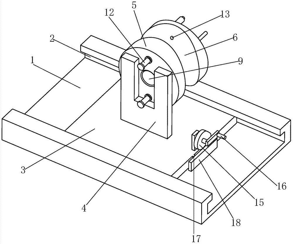
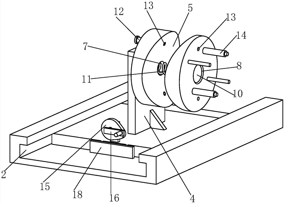
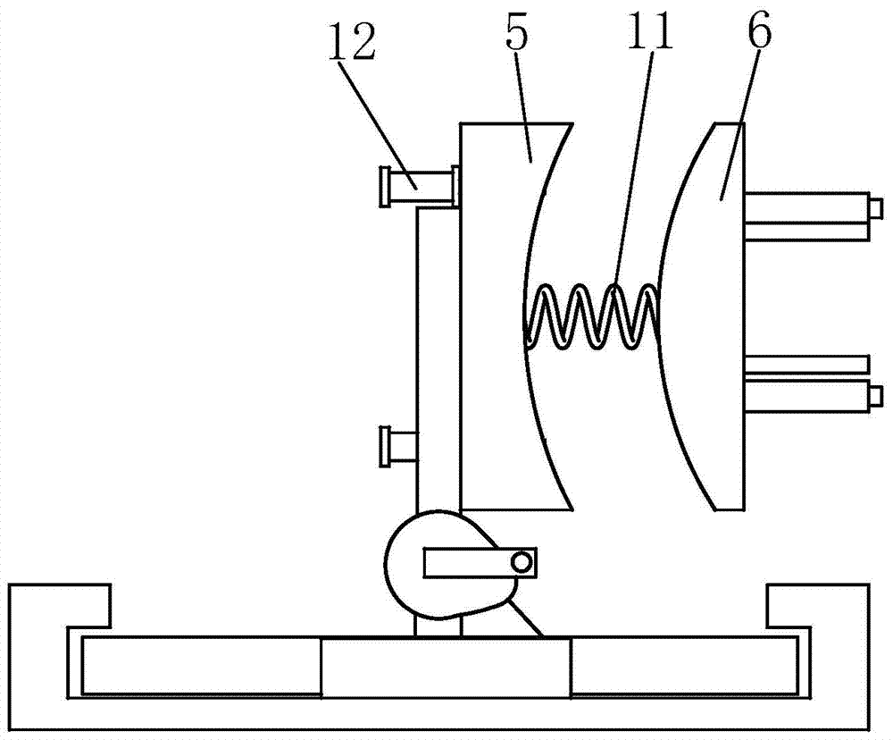
[0020] Such as Figure 1 to Figure 3 As shown, a fixture for vertical drilling of parts includes a base plate 1, a slideway 2 is provided on the front and rear sides of the base plate 1, a slide plate 3 is arranged inside the slide track 2, and a slide plate 3 is fixedly installed on the slide plate 3. There is a vertical plate 4, a fixed plate 5 is installed on the front end of the vertical plate 4, a movable plate 6 is provided in front of the fixed plate 5, a No. 1 through hole 7 is provided in the middle of the fixed plate 5, and the movable plate 6 The middle part is provided with a No. 2 through hole 8, the rear of the fixed plate 5 is provided with a No. 1 turn block 9, the front of the movable plate 6 is provided with a No. 2 turn block 10, and the front end of the No. 1 turn block 9 is equippe...


PUM


Abstract

The invention relates to a clamp for vertical drilling of a part. The clamp for vertical drilling of the part comprises a substrate. The front side and the rear side of the substrate are each provided with a slideway, a sliding plate is arranged in the slideways, and a vertical plate is fixedly installed on the sliding plate. A fixed disc is installed on the front end surface of the vertical plate, and a movable disc is arranged in front of the fixed disc. A first through hole is formed in the middle of the fixed disc, and a second through hole is formed in the middle of the movable disc. A first rotary block is arranged at the back of the fixed disc, and a second rotary block is arranged in front of the movable disc. A spring is installed at the front end of the first rotary block and penetrates through the first through hole and the second through hole to be installed on the rear end surface of the secondary rotary block. The fixed disc and the movable disc make contact with each other and are limited through arc surfaces. The method that the fixed disc and the movable disc are fixed through elastic positioning pins replaces the method in the prior art that a disc and cover type part is clamped through an air cylinder and then is machined, so that the trouble that when a machining surface of the disc and cover type part is changed, clamping needs to be released, and overturning and positioning are conducted again is saved. The machining efficiency is improved.

Description

technical field [0001] The invention relates to the technical field of fixtures for auto parts, in particular to a fixture for vertical drilling of parts. Background technique [0002] There are various types of auto parts, complex shapes, and difficult processing. Therefore, the production level of automobiles is also a direct reflection of the development level of the national processing and manufacturing industry. There are many auto parts and the assembly process is complicated. In the assembly process, in order to improve the assembly compactness and avoid the assembly difficulties caused by the narrow operating space, the mounting holes (such as threaded holes, pin holes, etc.) of many parts are used. Oblique or perpendicular to the extension direction of the part, so that the processor can process or assemble in a more comfortable processing posture. [0003] For example, during the processing of disc cover parts, the clamping of the disc cover is usually perpendicul...

Claims


Application Information

Patent Timeline
Patent Type & Authority Patents(China)
IPC IPC(8): B23Q3/06
CPCB23Q3/06
Inventor 张锋梁建华闫飞
Owner 芜湖全鑫模具机械股份有限公司
Why Eureka
Try Eureka