Scroll compressor.

A technology of scroll compressors and scroll disks, which is applied in the direction of rotary piston machinery, rotary piston pumps, mechanical equipment, etc., can solve the problems of increased movement speed, sharpness, and variable height of the cycle gap shape, and achieves Effect of less air recompression, reduced leakage velocity, and lower operating temperature

Active Publication Date: 2016-01-20
ATLAS COPCO AIRPOWER NV
View PDF5 Cites 6 Cited by
  • Summary
  • Abstract
  • Description
  • Claims
  • Application Information

AI Technical Summary

Problems solved by technology

[0051] In summary, the internal clearances in a scroll compressor greatly affect the efficiency of the scroll compressor during normal operation, and in known scroll compressors it is difficult to stay within the bounds and / or within the scroll The cyclic gap shape of local transverse internal clearances in rotary compressors is highly variable, or difficult to assess in advance
[0052] This problem is exacerbated with increasing temperature in scroll compressors, increasing power or increasing speed of motion of the rotor in the stator

Method used


Image

  • Scroll compressor.
  • Scroll compressor.
  • Scroll compressor.

Examples


Embodiment Construction

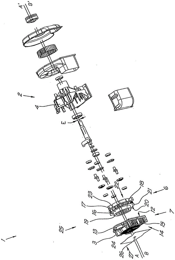
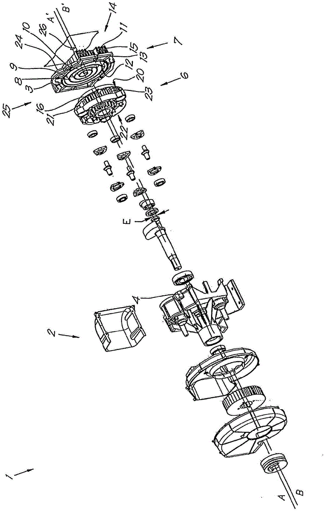
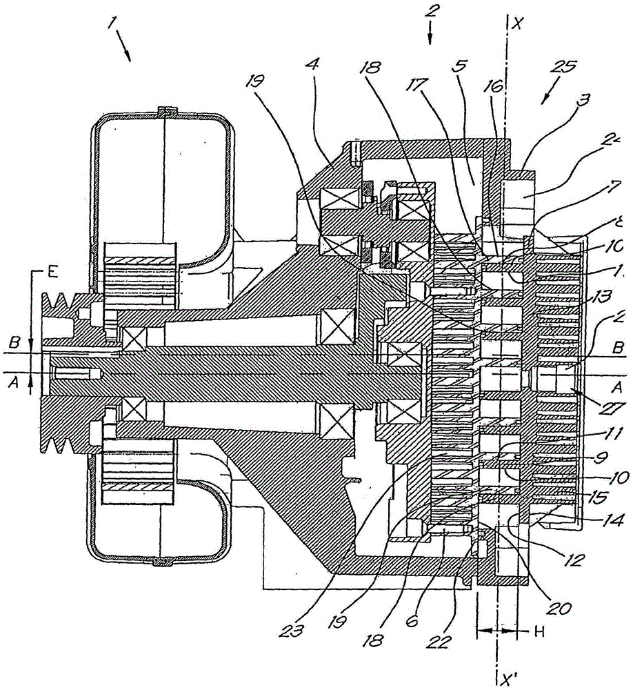
[0095] exist Figures 1 to 3 These elements shown in Fig. 1 give an oil-free scroll compressor 1 in an expanded and assembled state, and of the type to which the present invention relates.

[0096] The scroll compressor 1 has a housing 2, which in this case essentially consists of two parts, more specifically a part 3 and a part 4, which in the assembled state surround a space 5 in which a rotor 6 is fixed. .

[0097] Furthermore, part 3 forms a stator 7 which is immovably mounted in casing 2 and which comprises a fixed stator scroll with a central stator axis AA'.

[0098] The stator scroll 8 is formed by a stator strip 9 having two stator wings 10 and 11, namely an outward stator wing 10 and a stator scroll The center or central axis AA' of the disc 8 is turned inwardly towards the stator flanks 11 .

[0099] Furthermore, the stator band 9 is helically wound along its length and is fixed upright at a height H on the first side 12 of the stator plate 13 .

[0100] Cooling...


PUM


Abstract

Scroll compressor (1) with a stationary, stator scroll (8) and a movable rotor scroll (16) and a drive to move the rotor (6), whereby in each position places are formed with an instantaneous minimum opening (29) between the rotor scroll (16) and the stator scroll (8) whereby at each height (2) in a minimum opening (29) there is a local transverse internal clearance (S), whereby at least one of the stator flanks (10 / 11) or rotor flanks (18,19) comprises an adapted flank section (37-40) with an initial local stator flank deviation ([delta]T0i, AT0u) or rotor flank deviation ([delta]R0i / AR0u) that is different to zero at each point when the rotor (6) is stationary, and during nominal operation of the scroll compressor corresponding instantaneous final local stator flank deviations ([delta]Tfi,[delta]Tfu) or rotor flank deviations ([delta]Rfi,[delta]Rfu) whose absolute values are smaller.

Description

technical field [0001] This invention relates to scroll compressors. Background technique [0002] It is known that scroll compressors generally include the following elements: [0003] shell; [0004] Stator, which is immovably fixed in the housing and comprises a fixed stator scroll with a central stator axis, whereby the stator scroll is formed by a stator strip with two stator flanks, which is helical along its length Wrapped and fixed upright on the stator plate at a certain height; [0005] a rotor movably secured in the housing and comprising a rotor scroll having a central rotor axis and being formed from a rotor band having two rotor wings helically wound along its length, And fixed upright on the rotor plate at a certain height, whereby the rotor scroll and the stator scroll are fixed in each other between the stator plate and the rotor plate; [0006] a low pressure inlet located on the outer side of the scroll compressor; [0007] a high-pressure outlet loca...

Claims


Application Information

Patent Timeline
Patent Type & Authority Applications(China)
IPC IPC(8): F04C18/02
CPCF04C18/0246F04C2250/20F04C2270/17F04C18/0269F04C18/0215
Inventor B·莫恩斯K·斯图普
Owner ATLAS COPCO AIRPOWER NV
Why Eureka
Try Eureka