
Boring Fixture for Thin Parts

A technology for boring jig and thin parts, applied in the field of thin part boring jig, can solve the problems such as the inability to guarantee the perpendicularity between the inner hole and the end face, the labor intensity of the operator, and the long manual clamping time, so as to reduce the instability factor. , the structure is simple, the production cost is low

Active Publication Date: 2018-06-26
NANTONG HONGBO MACHINERY
View PDF5 Cites 0 Cited by
  • Summary
  • Abstract
  • Description
  • Claims
  • Application Information

AI Technical Summary

Problems solved by technology

[0004] 1. The wall of the workpiece is thin and the manual clamping force of the blank three-jaw chuck cannot be completely uniform. Too tight will cause the workpiece to deform, and too loose will cause the workpiece to loosen after the cutting force is applied, thereby damaging the jaws and breaking the tool;
[0005] 2. The manual clamping time is long, the labor intensity of the operator is high, and the benefit is low;
[0006] 3. The processing quality is poor, the size is not easy to control, and the perpendicularity between the inner hole and the end face cannot be guaranteed due to factors such as loose workpieces, and the pass rate is low, which brings difficulties to the subsequent process, and 81% meet the process requirements;
[0007] 4. The cost is high, only this process costs 0.45 yuan per piece

Method used


Image

  • Boring Fixture for Thin Parts
  • Boring Fixture for Thin Parts

Examples


Embodiment Construction

[0017] In order to more clearly illustrate the technical solutions in the embodiments of the present invention or the prior art, the following will briefly introduce the drawings that need to be used in the description of the embodiments or the prior art. Obviously, the accompanying drawings in the following description are only These are some embodiments of the present invention. For those skilled in the art, other drawings can also be obtained according to these drawings without any creative effort.

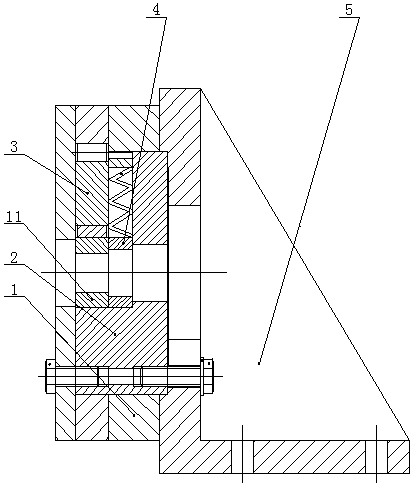
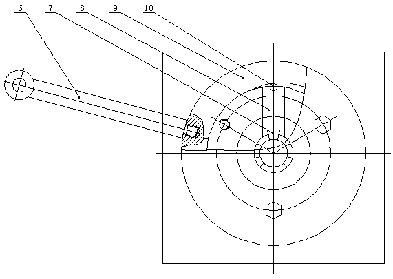
[0018] see as figure 1 —— figure 2 As shown, this specific embodiment adopts the following technical scheme: it includes a fixed sleeve 1, a clamp body 2, an end cover 3, a positioning ring 4, a bracket 5, a handle 6, a chuck 7, a slider 8, a clamping ring 9, a roller Column 10; the clamp body 2 and the bracket 5 are fixedly connected by bolts; the outer wall of the clamp body 2 is provided with a fixed sleeve 1, and a positioning ring 4 is installed in the clamp body 2; the ...


PUM


Abstract

The invention provides a thin piece boring clamp and relates to the technical field of machine manufacturing. The thin piece boring clamp comprises a fixing sleeve, a clamp body, an end cover, a positioning ring, a support, a handle, a chuck, a slide block, a clamping ring and a pin roller, wherein the clamp body is fixedly connected with the support through a bolt; the outer wall of the clamp body is sleeved with the fixing sleeve, and the positioning ring is mounted in the clamp body; the pin roller and the chuck are arranged at the upper end and the lower end of the slide block respectively, the slide block and the a spring are mounted in the clamp body; the pin roller and the periphery of the clamp body are sleeved with the clamping ring, and the end cover is arranged on one side of the clamp ring; one end of the handle is connected with the clamp ring. According to the thin piece boring clamp, the pneumatic clamping force is uniform and stable, a workpiece doesn't deform and loosen, a self-locking function is realized, damage to a tool and the chuck is reduced, the tool cannot be damaged abnormally, and hard and tough purposes are realized.

Description

technical field [0001] The invention relates to the technical field of mechanical manufacturing, in particular to a thin piece boring fixture. Background technique [0002] Since the existing equipment only has C6136 and C6140 lathes, limited by the equipment conditions, the lathes can only be clamped with three claws for boring and lathing. The following defects were found through production: [0003] shortcoming: [0004] 1. The wall of the workpiece is thin and the manual clamping force of the blank three-jaw chuck cannot be completely uniform. Too tight will cause the workpiece to deform, and too loose will cause the workpiece to loosen after the cutting force is applied, thereby damaging the jaws and breaking the tool; [0005] 2. The manual clamping time is long, the labor intensity of the operator is high, and the benefit is low; [0006] 3. The processing quality is poor, the size is not easy to control, and the perpendicularity between the inner hole and the end ...

Claims


Application Information

Patent Timeline
Patent Type & Authority Patents(China)
IPC IPC(8): B23Q3/06
CPCB23Q3/062
Inventor 袁建华马建姚文凤袁兰华
Owner NANTONG HONGBO MACHINERY
Learn More