Waste liquor collector

A waste liquid collection and waste liquid tank technology, applied in chemical instruments and methods, smoke removal, cleaning methods and utensils, etc., can solve the problems of obvious secondary pollution risks, heavy cleaning operations, and low work efficiency, and achieve cleaning operations. Simple, avoid manual connection of pipelines, and avoid the effect of secondary pollution

Active Publication Date: 2016-03-30
HANGZHOU ZHONGYA MACHINERY CO LTD
View PDF11 Cites 0 Cited by
  • Summary
  • Abstract
  • Description
  • Claims
  • Application Information

AI Technical Summary

Problems solved by technology

Throughout the entire cleaning process, it can be found that the cleaning cycle is too long and the cleaning operation is heavy due to the waste liquid discharge operation, which has the disadvantages of low work efficiency and obvious risk of secondary pollution

Method used


Image

  • Waste liquor collector
  • Waste liquor collector
  • Waste liquor collector

Examples


Embodiment Construction

[0017] The first embodiment of the present invention.

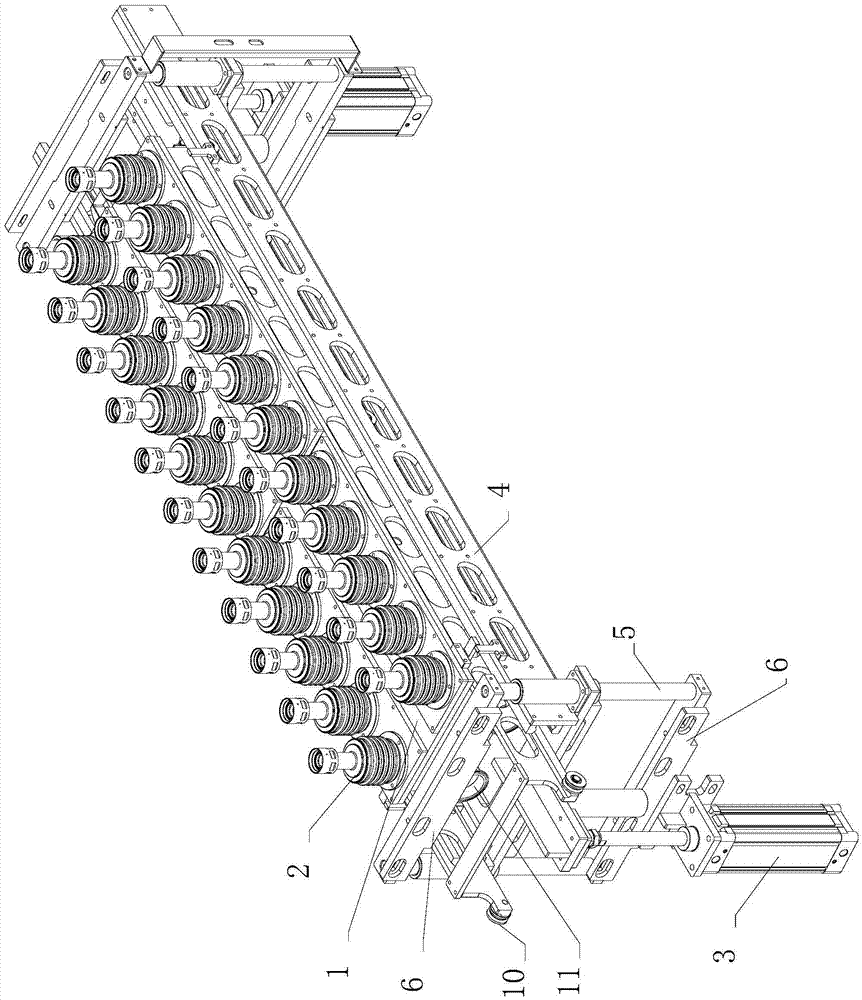
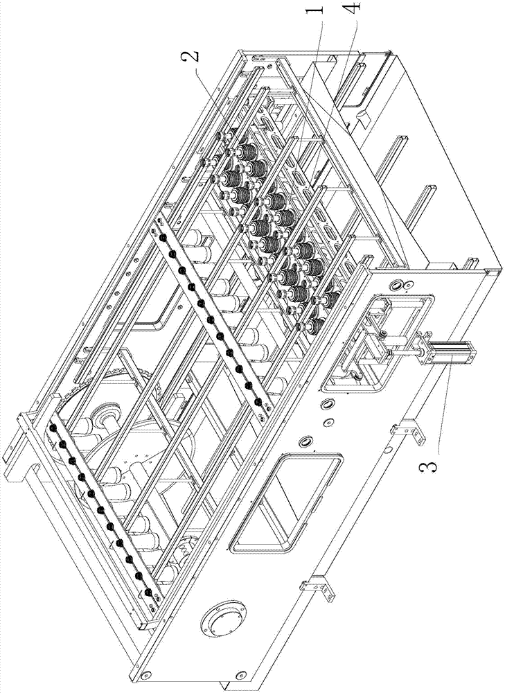
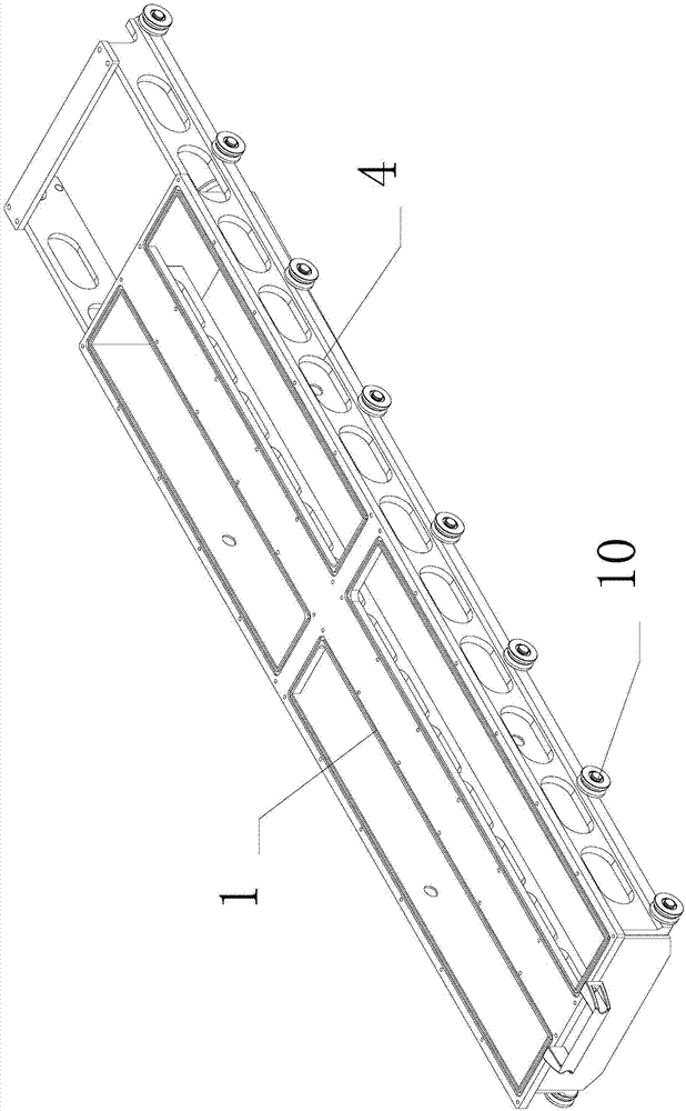
[0018] The linear filling device is equipped with a filling valve, a circulation conveying mechanism, a container clamping mechanism, and a waste liquid collector.

[0019] The circulation conveying mechanism includes two chains arranged in parallel on the runners, and the chains are distributed in a straight line between the runners to form a linear conveying area; the runners are movably connected to the bracket on which the circulation conveying mechanism is installed. The running wheels at one end are connected to the motor providing power through the rotating shaft, and the two chains can run synchronously after the motor rotates. The container clamping mechanism is composed of a plurality of clamping templates used in pairs. Each pair of clamping templates is movably connected to the chain through the connection of pin shafts inserted into pin holes. The clamping templates move reciprocatingly with the chain. The b...


PUM


Abstract

The invention discloses a waste liquor collector. The waste liquor collector is provided with a lifting component, a waste liquor tank and a connecting part, wherein the waste liquor tank is fixedly mounted on the lifting component, the connecting piece adopts a tubular structure, one end of the tubular structure is provided with a connector used for inputting a waste liquor, the other end of the tubular structure is fixedly connected with the waste liquor tank, the inner cavity of the waste liquor tank is communicated with the inner cavity of the connecting piece, a liquor drainage port is formed in the waste liquor tank, and the connecting part is movably connected with a filling valve through the lifting component. By controlling a connecting process, the waste liquor collector can quickly transfer a waste liquor discharging function onto a linear filling device, therefore, the purpose of discharging waste liquor automatically is achieved, moreover, manually connecting pipelines can be avoided, the cleaning period is shortened greatly, and secondary pollution can be avoided.

Description

technical field [0001] The invention relates to a waste liquid collector. Background technique [0002] There is a CIP cleaning function on the linear filling device. This function benefits from the ingenious pipeline design, so that the pipeline for conveying milk and the pipeline for conveying cleaning agent form a switch structure. When the filling function is realized, the pipeline only delivers When the milk and the cleaning function are realized, the pipeline only transports the cleaning agent. The treatment of waste liquid after cleaning is the weak point in the use process of the linear filling device in the prior art, because the waste liquid needs to be discharged from the filling valve of the linear filling device. In the prior art, each filling valve is paired An infusion tube through which waste liquid is discharged outwards. The infusion tube needs to be installed manually before the waste liquid is discharged. Usually, the linear filling device has multiple ...

Claims


Application Information

Patent Timeline
Patent Type & Authority Applications(China)
IPC IPC(8): B08B15/00
CPCB08B15/00
Inventor 史中伟史正王正发
Owner HANGZHOU ZHONGYA MACHINERY CO LTD
Why Eureka
Try Eureka