Stable dynamic linear movement generating device

A technology of linear motion and generating device, applied in the direction of hoisting device, hoisting device, etc., can solve the problems of bulky equipment, single parameters, short movement stroke, etc., and achieve the effect of high safety factor

Inactive Publication Date: 2016-05-04
BEIHANG UNIV
View PDF6 Cites 3 Cited by
  • Summary
  • Abstract
  • Description
  • Claims
  • Application Information

AI Technical Summary

Problems solved by technology

The vibrating table can only produce small displacement and low-amplitude vibration, the motion stroke is short, the speed amplitude is small, and it cannot simulate most linear motion states; the air cannon uses the principle of aerodynamics, the working medium is air, and is composed of a differential pressure device and an automatic control device. The rapid exhaust valve can instantly convert the air pressure energy into the air jet kinetic energy, which can produce a strong impact force. The equipment is bulky, and the moving target is destroyed after being launched. It is impossible to install other sensors on it, and the cost is relatively high. There is a certain risk; the drop device can only provide a free fall process, and the form is single; the collision device uses the mechanical collision of objects to generate impact motion, the controllability is poor, and the energy recovery form is complicated in a limited space
To sum up, the current linear motion generating device has disadvantages such as single parameter, poor controllability, high cost or low safety factor.

Method used


Image

  • Stable dynamic linear movement generating device
  • Stable dynamic linear movement generating device
  • Stable dynamic linear movement generating device

Examples


Embodiment Construction

[0044] Combine below figure 1 , figure 2 , image 3 and Figure 4 , to further illustrate the present invention.

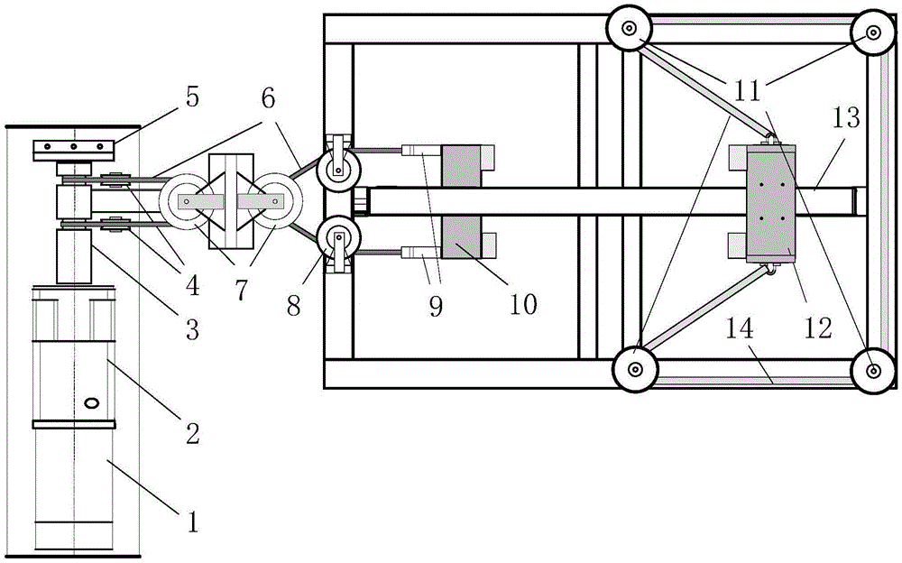
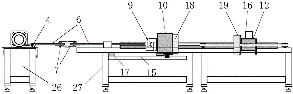
[0045] Such as figure 1 and figure 2As shown, a stable dynamic linear motion generating device of the present invention includes three parts: a drive module, a motion module and a support module. The relationship between them is: the supporting module is the supporting platform of the driving module and the motion module, and limits the movement space range of the driving module and the motion module; the driving module is responsible for driving the motion module to store potential energy.

[0046] The drive module includes a three-phase stepping motor 1, a motor reducer 2, a cable reel 3, a cable 6, a cable height guide pulley 4, a cable connection pulley 7, a cable width guide pulley 8, a tension sensor 9, and a ball slider 10 , ball slider guide rail 15, electromagnetic lock 18 and photoelectric limit device 17; the relationship between them is: the th...


PUM


Abstract

The invention provides a stable dynamic linear movement generating device. The stable dynamic linear movement generating device consists of three parts including a driving module, a moving module and a supporting module; the driving module comprises a three-phase stepping motor, a motor reducer, a cable reel, a cable, a cable height guiding pulley, a cable connection pulley, a cable width guiding pulley, a tension sensor, a ball slider, a ball slider guide track, an electromagnetic lock and a photoelectrical limiting device; the moving module comprises an air floatation module, an air floatation guide track, an auxiliary equipment fixing seat, an electromagnetic lock attracting plate, an elastic rope and an elastic rope guiding pulley; and the supporting module comprises a motor platform and a guide track platform. A dynamic linear movement state generated by the device can be adjusted and set in a certain range, a movement process is stable and free of vibration, energy is recycled safely and reliably, the device is simple in structure, and can be detached, and movement and transportation are facilitated.

Description

technical field [0001] The invention relates to a motion generating device, in particular to a stable dynamic linear motion generating device. It belongs to the technical field of motion parameter traceability. Background technique [0002] Linear motion is one of the common motion states. In national defense, military, industrial production and daily life, there is a need to measure the state parameters of linear motion. For example: during the missile launch process, the velocity and acceleration of the inner ballistic exit barrel (missile launch barrel / box) are important parameters for judging whether the performance of the launch system is normal and whether the launch process is successful or not. In the steel rolling production line, the speed monitoring of the steel billet entering the furnace can reduce the scrap rate, thereby reducing the production cost, optimizing the production process, predicting and eliminating hidden troubles. Many special engineering applic...

Claims


Application Information

Patent Timeline
Patent Type & Authority Applications(China)
IPC IPC(8): B66F19/00
CPCB66F19/00
Inventor 孟晓风张耀平聂晶王国华
Owner BEIHANG UNIV
Why Eureka
Try Eureka