
Transfer capability matching-based hub connection bus station configuring method

A bus and hub technology, applied in the direction of instruments, data processing applications, forecasting, etc., can solve the problems of lack of scientific methods, judgments, etc.

Active Publication Date: 2016-05-04
JIANGSU INST OF URBAN PLANNING & DESIGN
View PDF3 Cites 6 Cited by
  • Summary
  • Abstract
  • Description
  • Claims
  • Application Information

AI Technical Summary

Problems solved by technology

For issues such as whether to set up the first and last bus stops, the number and area of ​​the set up, the relevant regulations only provide principled regulations. Stations should be set up on land other than urban roads, and the area of ​​each site can be calculated as 1,000-1,400 square meters"; "Code for Design of Urban Road Public Transport Stations, Stations, and Plants (CJJ / T15-2011)" stipulates that "in the train It is advisable to set up the first and last stations or public transportation hub stations shared by multiple lines at stations, passenger terminals, long-distance passenger stations, large commercial areas, subdistrict centers, parks, gymnasiums, theaters and other activity gathering places or at the connection points of multiple transportation modes; The first and last stations of public transportation should be set within 50m of the main entrances and exits of long-distance passenger stations, railway stations, and passenger terminals”; in general, the relevant regulations are relatively general, and the current quantitative scientific methods are still relatively lacking. Judging whether to set up the first and last bus stops according to the actual demand of passenger flow, and determine how many first and last bus stops and the area of ​​the first and last bus stations need to be set up

Method used


Image

  • Transfer capability matching-based hub connection bus station configuring method
  • Transfer capability matching-based hub connection bus station configuring method
  • Transfer capability matching-based hub connection bus station configuring method

Examples


Embodiment Construction

[0054] Taking "Suzhou Industrial Park Comprehensive Traffic Planning (2012-2030)" as an example, the hub connection bus station setting in the west of the lake CBD area relying on the subway station, the technical solution of the present invention will be further described in detail below:

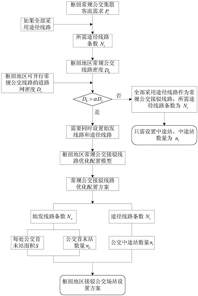
[0055] Such as figure 1 As shown, the present invention discloses a hub connection bus station setting method based on transfer capacity matching, which includes the following steps:

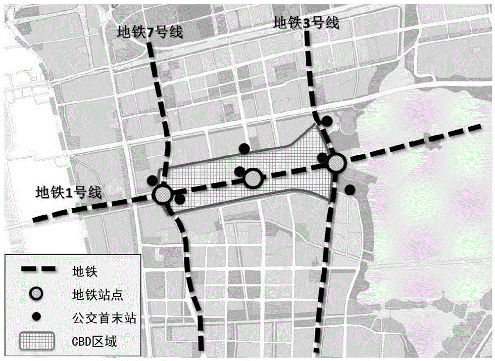
[0056] 1. The Huxi CBD of Suzhou Industrial Park includes three subway lines: Metro Line 1, Line 3 and Line 7. There are 3 subway stations within the CBD area: Central Park Station (Metro Line 1 and Metro Line 7), Xinghai Street Station (Metro Line 1), Xinggang Street Station (Metro Line 1, Metro Line 3), in view of the characteristics of large passenger flow demand in the CBD area, 3 hubs should be built in combination with 3 subway stations, such as figure 2 As shown; according to the traffic model calcu...


PUM


Abstract

The invention discloses a transfer capability matching-based hub connection bus station configuring method. The method comprises the steps of calculating and confirming the hub conventional bus feeder passenger traffic demand according to traffic surveys or traffic models; assuming that way lines are all adopted as conventional bus connection lines of hub areas, confirming the required number of the way lines and the density of conventional bus lines of the hub areas; building a method for judging whether starting lines and the way lines are needed to be simultaneously set or not; building an optimal configuration model of the conventional bus connection lines of the hub areas, confirming the number of the starting lines and the number of the way lines and obtaining an optimal configuration scheme of the conventional bus connection lines of the hub areas; and confirming the area and the number of bus original and terminal stations and the number of bus halfway stations and obtaining the connection bus station configuring scheme of the hub areas. By adopting the method disclosed by the invention, the purposes of intensively utilizing the public traffic resource and avoiding the road traffic jam of the hub areas are achieved through the optimal configuration of the conventional bus connection lines and stations.

Description

technical field [0001] The invention relates to a hub-connected bus station setting method based on transfer capacity matching, which belongs to the field of urban traffic planning. Background technique [0002] Hub areas generally have a large demand for passenger flow collection and distribution, and a certain number of conventional bus feeder lines need to be configured. Conventional bus connection lines include originating lines and passing lines. The passenger flow collection and distribution capacity of these two connecting lines is quite different, and the passing lines can use the intermediate stations set up on the road to realize passenger flow collection and distribution, while the starting line The line needs to use the first and last stations of the bus for passenger flow collection and distribution. At present, these two conventional bus connection lines are generally configured according to experience, and the following situations often occur: if too many bus...

Claims


Application Information

Patent Timeline
IPC IPC(8): G06Q10/04G06Q50/30
CPCG06Q10/04G06Q50/40
Inventor 姜军王树盛曹国华黄富民
Owner JIANGSU INST OF URBAN PLANNING & DESIGN
Learn More