E-STATCOM-based forced power oscillation suppression method and system

A technology of forced power oscillation and power control module, which is applied in the direction of reducing/preventing power oscillation, flexible AC transmission system, AC network load balancing, etc., and can solve the problems of expansion of accident scope, difficulty, and immature technology of power disturbance source location, etc. , to achieve a good suppression effect, improve the system damping, and suppress the effect of forced power oscillation

Active Publication Date: 2016-05-11
SOUTHEAST UNIV
View PDF4 Cites 4 Cited by
  • Summary
  • Abstract
  • Description
  • Claims
  • Application Information

AI Technical Summary

Problems solved by technology

These methods need to be operated by the controller after the oscillation occurs for a certain period of time, and the forced power oscillation starts quickly, so if the operation is not timely, it may lead to the expansion of the scope of the accident
In addition, because the power disturbance source location technology in the actual system is not very mature, it is also difficult to find the disturbance source in time and accurately for control.

Method used


Image

  • E-STATCOM-based forced power oscillation suppression method and system
  • E-STATCOM-based forced power oscillation suppression method and system
  • E-STATCOM-based forced power oscillation suppression method and system

Examples


Embodiment Construction

[0032] The technical solution of the present invention will be further introduced below in conjunction with specific embodiments.

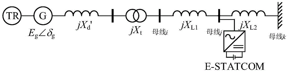
[0033] The following takes a typical single-machine infinite bus system as an example to illustrate the specific implementation of the present invention. A stand-alone infinity system with E-STATCOM installed such as figure 2 As shown, the steam turbine, the speed control system and the synchronous generator are connected to the bus i through a transformer. Among them, the steam turbine and the speed control system are represented by TR, and the synchronous generator consists of a voltage source and a transient reactance (X d ') means that the amplitude of the voltage source is E g , The phase angle is δ g . E-STATCOM is installed on bus j and connected to the infinite bus k through a tie line. The impedance between bus i and bus j is jX L1 , The impedance between bus j and bus k is jX L2 . The synchronous generator has a rated capacity of 200MW, a ...


PUM


Abstract

The invention discloses an E-STATCOM-based forced power oscillation suppression method and system, and further discloses an E-STATCOM-based forced power oscillation suppression system. The E-STATCOM-based forced power oscillation suppression system comprises a signal collection module, wherein an input end of the signal collection module is connected with a left power transmission line and a right power transmission line, which are connected with an E-STATCOM mounting bus, respectively; an output end of the signal collection module is connected with the input end of a control signal selection module; the output end of the control signal selection module is connected with the input end of an oscillation identification module, the input end of a reactive power control module and the input end of an active power control module respectively; the output end of the oscillation identification module is connected with the input end of the reactive power control module and the input end of the active power control module respectively; and the output end of the reactive power control module and the output end of the active power control module are connected with an E-STATCOM. Manual operation is not needed; and the E-STATCOM-based forced power oscillation suppression method and system have good suppression effects on forced power oscillation.

Description

Technical field [0001] The invention relates to the technical field of power system stability and control, in particular to an E-STATCOM-based method and system for suppressing forced power oscillation. Background technique [0002] Under the basic pattern of power transmission from west to east and north-south interconnection, my country will gradually form a large-scale interconnected power grid across the country, which makes the problem of power oscillations in the power system increasingly prominent. The traditional power oscillation is mainly the low-frequency oscillation of the negative damping mechanism caused by insufficient system damping, and its suppression measures are to improve the system damping. However, in recent years, some power oscillations cannot be explained by the negative damping mechanism. These oscillations still occur even when the system damping device is installed. Research has found that these oscillations are forced power oscillations, which are ca...

Claims


Application Information

Patent Timeline
Patent Type & Authority Applications(China)
IPC IPC(8): H02J3/24H02J3/28
CPCH02J3/24H02J3/28Y02E40/10
Inventor 蒋平冯双吴熙范子恺
Owner SOUTHEAST UNIV
Why Eureka
Try Eureka