Valley conduction control circuit and control method thereof

A conduction control circuit, wave trough technology, applied in the direction of electrical components, high-efficiency power electronic conversion, output power conversion devices, etc., can solve the problems of no improvement in efficiency, limited input voltage, etc., to achieve jitter and improve electromagnetic interference , The effect of improving energy efficiency

Active Publication Date: 2018-08-28
SHENZHEN NANYUN MICROELECTRONICS CO LTD
View PDF3 Cites 0 Cited by
  • Summary
  • Abstract
  • Description
  • Claims
  • Application Information

AI Technical Summary

Problems solved by technology

Regardless of the input high voltage or input low voltage, the amplitude of the jitter and the period of the jitter are the same, and it can disperse the energy of electromagnetic interference. Therefore, this technology is not limited by the input like the valley conduction. Disadvantages of voltage size
However, frequency dithering technology does not have the advantage of improving efficiency.

Method used


Image

  • Valley conduction control circuit and control method thereof
  • Valley conduction control circuit and control method thereof
  • Valley conduction control circuit and control method thereof

Examples


Embodiment 1

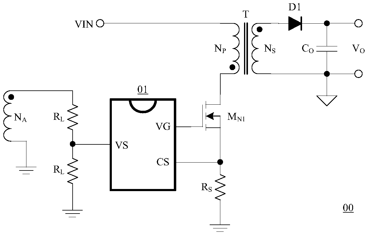
[0043] figure 1 It is a schematic block diagram of a flyback ACDC topology switching power supply. The switching power supply 00 system includes a transformer T, which has a primary winding N P , Secondary winding N S And auxiliary winding N A , Used to transfer energy and signal feedback; power input terminal VIN, primary ground, control system 01, first resistor R H , The second resistor R L , The first N-type MOS tube MN1, the third resistance sampling resistor R S , The first diode D1, the first capacitor Co, the secondary side output positive voltage terminal, and the secondary side ground. The first end of the primary winding NP of the transformer T, the second end of the secondary winding NS, and the first end of the auxiliary winding NA are ends of the same name. Description of primary side connection relationship: primary side winding N P The first terminal is connected to the power input voltage VIN, the second terminal is connected to the drain of the first N-type MOS...


PUM


Abstract

The present invention provides a novel frequency jittering valley conduction control system, which not only has the characteristics of valley conduction function, but also can realize the frequency shaking function within the full input voltage range and within the full load. The energy of the interference is dispersed in the frequency range of the entire frequency shaking range, thereby minimizing the influence of electromagnetic interference and improving the overall performance of the controller, and the control of the two technologies can be used for circuit multiplexing, which can save a lot of energy. A large part of the wafer increases the application rate.

Description

Technical field [0001] The present invention relates to a switching power supply, in particular to a valley conduction control circuit and a control method thereof for controlling the switching tube to be turned on and off at a suitable time. Background technique [0002] With the rapid development of science and technology, the use of consumer electronics has become more and more popular, and the integration of transistors is advancing in accordance with Moore's law. The number of devices contained in the same wafer area is increasing, and the device size is also increasing. Small, this not only leads to higher and higher energy requirements, but also lowers the power supply voltage used by the current integrated circuits, and the signal driving ability becomes weaker, which also leads to the chip’s resistance to electromagnetic interference. The ability requirements have become more stringent. In the current ACDC switching power supply industry, there are many ways to improve ...

Claims


Application Information

Patent Timeline
Patent Type & Authority Patents(China)
IPC IPC(8): H02M7/217H02M1/44
CPCH02M1/44H02M7/217H02M1/0041H02M1/0054Y02B70/10
Inventor 唐盛斌曾正球
Owner SHENZHEN NANYUN MICROELECTRONICS CO LTD
Why Eureka
Try Eureka