Supercharge Your Innovation With Domain-Expert AI Agents!

Air flow control arrangement for pulverizers

A technology of airflow control and pulverizer, applied in the direction of grain processing, etc., can solve problems such as unsatisfactory

Active Publication Date: 2016-05-11
GENERAL ELECTRIC TECH GMBH
View PDF5 Cites 5 Cited by
  • Summary
  • Abstract
  • Description
  • Claims
  • Application Information

AI Technical Summary

Problems solved by technology

[0005] Such conventional designs may be very practical and may generally be considered adequate for their intended purpose, but may be unsatisfactory in terms of being able to be replaced in an economical and convenient manner in the event of wear and tear

Method used


Image

  • Air flow control arrangement for pulverizers
  • Air flow control arrangement for pulverizers
  • Air flow control arrangement for pulverizers

Examples


Embodiment Construction

[0023] For a thorough understanding of the present disclosure, reference is made to the following detailed description, including the appended claims, taken in conjunction with the foregoing accompanying drawings. In the following description, for purposes of explanation, numerous specific details are set forth in order to provide a thorough understanding of the present disclosure. It will be apparent, however, to one skilled in the art that the present disclosure may be practiced without these specific details. In other instances, structures and devices are only shown in block diagram form in order to avoid obscuring the disclosure. References in this specification to "one (one) embodiment", "an (an) embodiment", "another embodiment", "various embodiments" mean that the specific functions, structures described in connection with the embodiment or features are included in at least one embodiment of the present disclosure. The appearances of the phrase "in one embodiment" in ...


PUM


Abstract

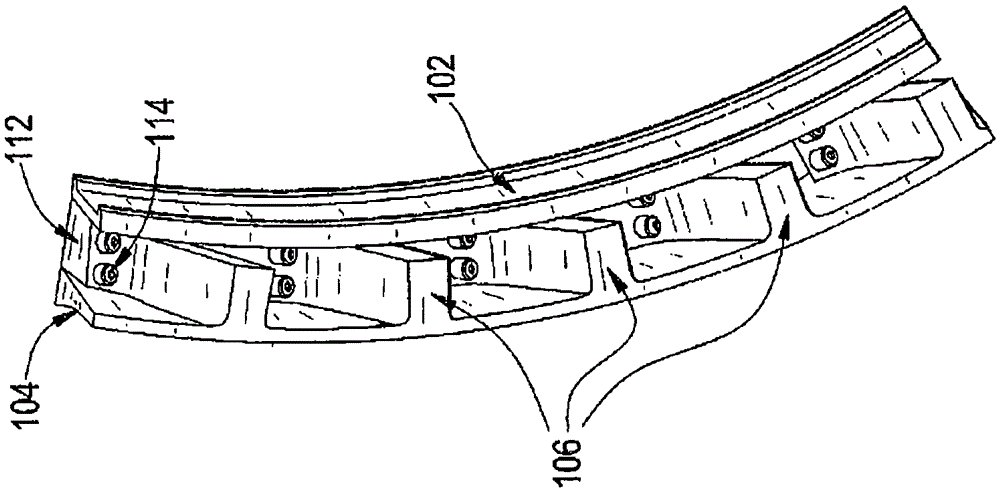
An air flow control arrangement for a pulverizer includes an inner ring segment (102), an outer ring segment (104), a plurality of vanes (106), and a plurality of wingtips (108). The inner and outer ring segments are adaptably configured in a spaced relation to each other. Further, the plurality of vanes (106) is spaced apartly arranged between the inner and outer ring segments (102, 104) to form flow ducts. Furthermore, each wingtip (108) of the plurality of wingtip is detachably attached to a respective vane (106) of the plurality of vanes to be adaptably replaceable or changeable.

Description

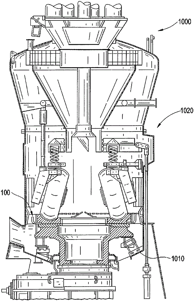
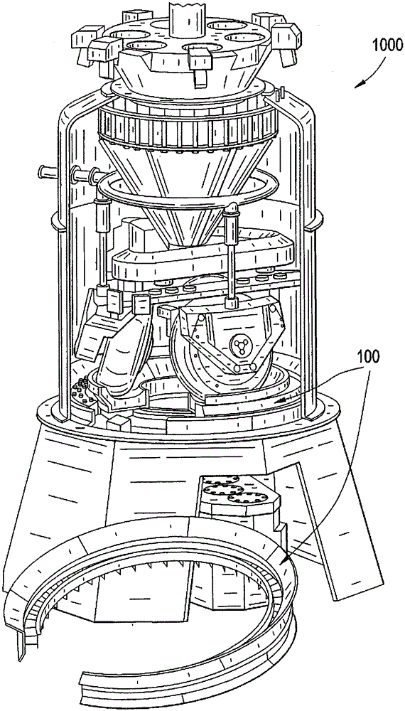
technical field [0001] The present disclosure relates to the field of coal pulverizers and, more particularly, to an airflow control arrangement in a roll torace coal pulverizer. Background technique [0002] The airflow control arrangement in the pulverizer (also commonly referred to as a rotary throat, gas port, or vane wheel) configures the gas conduits to direct a controlled airflow into the pulverizer grinding area of ​​the pulverizer to assist in the efficient pulverization of the coal. Crush and dry and remove with pyrite. [0003] Typically, such an arrangement includes an inner ring and an outer ring, and various vanes arranged in spaced relationship between the outer ring and the inner ring. The inner ring is joined to the pulverizer grinding area and the outer ring is cooperatively welded to the inner ring with the various blades. In addition, wingtips are also welded between the inner and outer rings to the respective blades for speed control and alignment of t...

Claims


Application Information

Patent Timeline
Patent Type & Authority Applications(China)
IPC IPC(8): B02C15/00
CPCB02C15/001B02C15/04
Inventor P·M·科森
Owner GENERAL ELECTRIC TECH GMBH
Features
  • R&D
  • Intellectual Property
  • Life Sciences
  • Materials
  • Tech Scout
  • Unparalleled Data Quality
  • Higher Quality Content
  • 60% Fewer Hallucinations
Learn More