Highlight face milling cutterhead and highlight face milling cutter

A face milling cutter and face milling cutter technology, applied in milling cutters, manufacturing tools, milling machine equipment, etc., can solve the problems of high surface roughness requirements, low processing efficiency, poor mirror effect, etc., to improve the highlight effect, The effect of improving processing efficiency and ensuring balance

Active Publication Date: 2016-07-20
GUANGZHOU HAOZHI ELECTROMECHANICAL
View PDF6 Cites 7 Cited by
  • Summary
  • Abstract
  • Description
  • Claims
  • Application Information

AI Technical Summary

Problems solved by technology

Manufacturers often encounter a series of problems when processing high-gloss workpieces, such as: the surface roughness requirements are too high, and the traditional process cannot meet the technical requirements; the traditional polishing process has low efficiency, high cost, and high labor intensity; the polishing workshop environment Poor, unable to remove product surface texture, etc., making it difficult to improve the market competitiveness of products
At present, the high-gloss engraving and milling processing in the market adopts a straight-shank single-edged diamond chamfering high-gloss knife, with a speed of S=6.5-75,000 rpm, a feed rate of F=3000-5000mm / min, and a cutting amount of 0.02-0.05mm. The high-performance air-floating electric spindle achieves the best effect Ra=50nm, and the visual effect is uniform and bright, but there are still shortcomings of poor mirror effect and low processing efficiency after metal processing

Method used


Image

  • Highlight face milling cutterhead and highlight face milling cutter
  • Highlight face milling cutterhead and highlight face milling cutter
  • Highlight face milling cutterhead and highlight face milling cutter

Examples


Embodiment 1

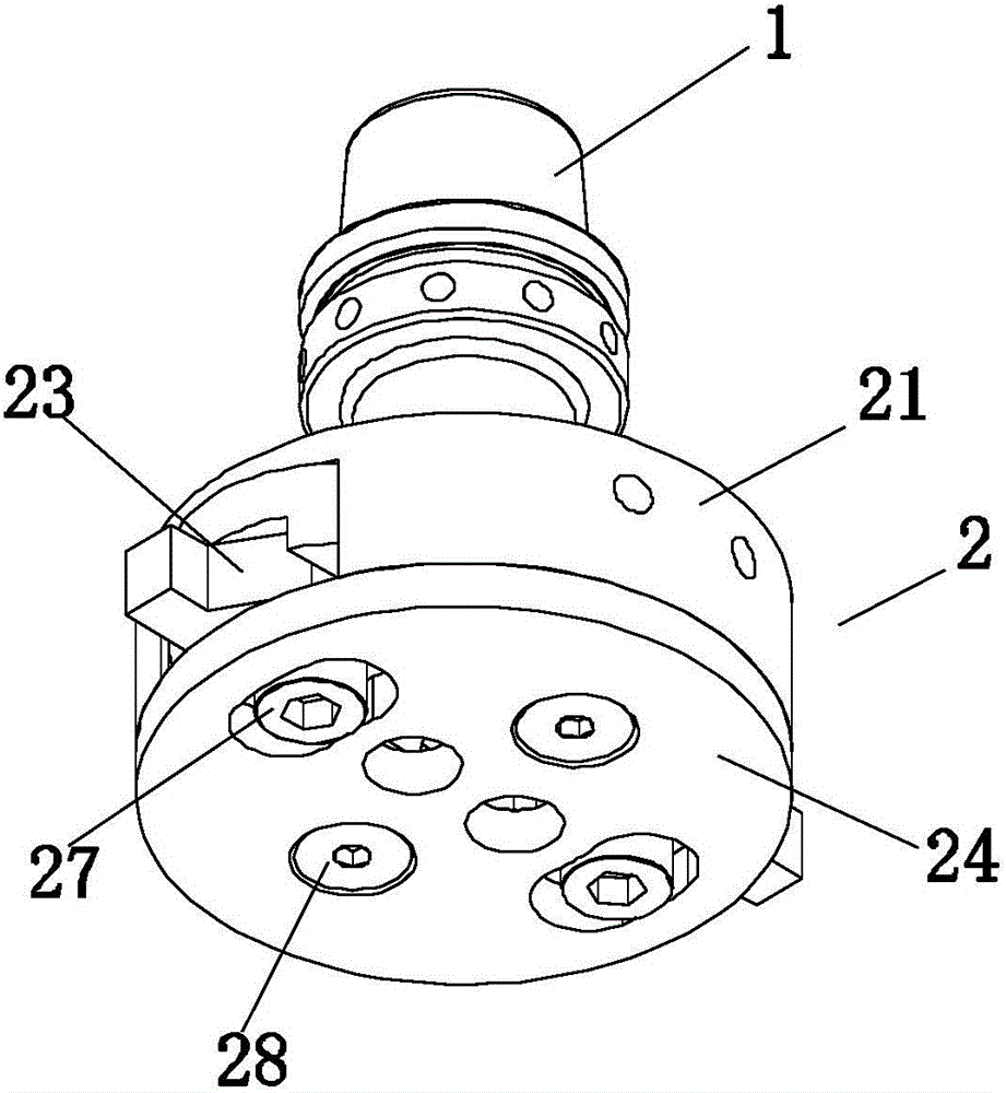
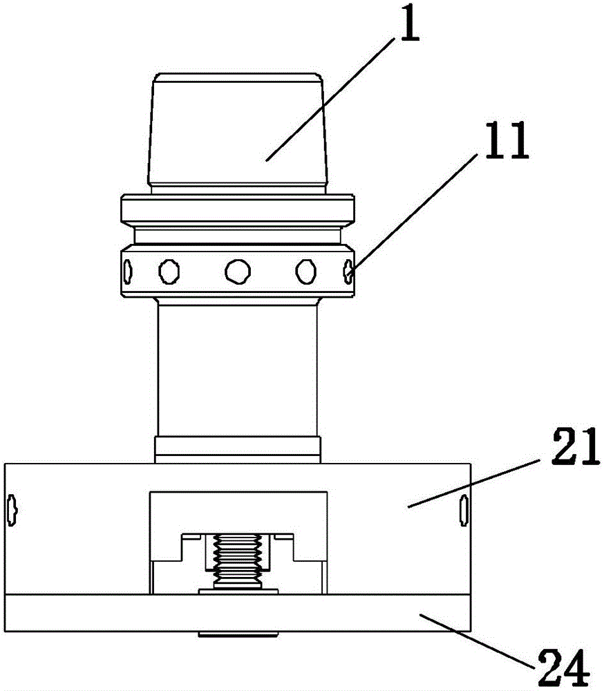
[0030] refer to Figure 1-3 , This embodiment provides a high-gloss surface milling tool, including a tool handle 1 and a cutter head 2, the tool handle 1 and the cutter head 2 are fixedly connected by bolts; the tool handle 1 is an HSKE25 tool handle. The knife handle 1 is provided with several balance weight holes 11 distributed evenly along the circumference of the knife handle. The cutterhead 2 is a high-gloss milling cutterhead.

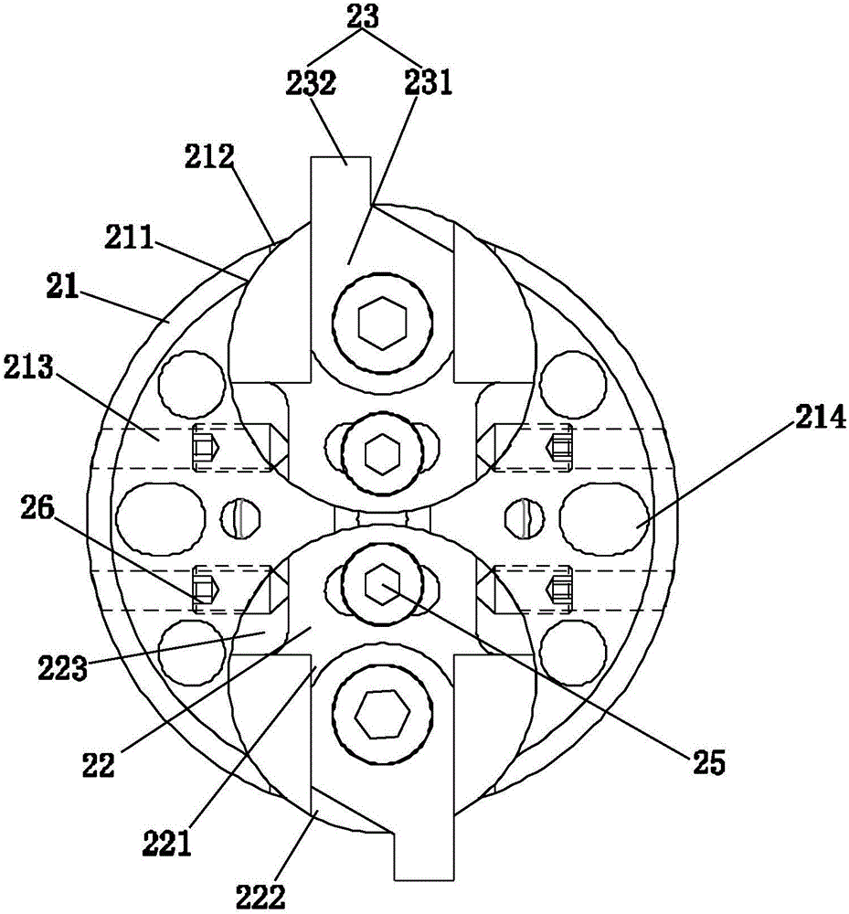
[0031] The high-gloss face milling cutter disc includes a face milling cutter disc body 21, two rotating discs 22, two milling cutters 23 and a cover plate 24;

[0032] Two circular grooves 211 are symmetrically distributed along the center of the face milling cutter body 21 on the end face of the face milling cutter body 21 , and each circular groove 211 is provided with a first gap that runs through the side wall of the face milling cutter body 21 212;

[0033] Each rotating disk 22 is installed in one of the circular grooves 211 in a clear...


PUM


Abstract

The invention discloses a highlight face milling cutterhead. The highlight face milling cutterhead comprises a face milling cutterhead body, two rotating plates, two milling cutters and a cover plate. Two circular grooves are symmetrically distributed in the end face of the face milling cutterhead body. Each rotating plate is installed in one circular groove and provided with a milling cutter installation groove. Each milling cutter comprises a milling cutter handle and a milling cutter head arranged at one end of the milling cutter handle. The milling cutter handles of the milling cutters are fixedly installed in the milling cutter installation grooves. The milling cutter head of each milling cutter sequentially penetrates a second notch and a first notch and extends outwards, wherein the second notch and the first notch correspond to the milling cutter head. The cover plate is fixedly connected with the end face of the face milling cutterhead body. The invention further discloses a highlight face milling cutter. By means of the highlight face milling cutterhead and the highlight face milling cutter, the highlight effect of products can be improved, the mirror surface effect that Ra is smaller than or equal to 25 nm is achieved, and cutter patterns are eliminated; and an upper chamfer and a lower chamfer can be machined at the same time, the machining efficiency is improved, the balance performance of the whole cutterhead can be effectively ensured, and the subsequent balancing difficulty is lowered.

Description

technical field [0001] The invention relates to a cutter, in particular to a high-gloss surface milling cutter disc and a high-gloss surface milling cutter. Background technique [0002] With the progress of society, consumers have higher and higher requirements for product appearance design, and good high-gloss processing effect has become an important standard to measure the appearance quality of products. Manufacturers often encounter a series of problems when processing high-gloss workpieces, such as: the surface roughness requirements are too high, and the traditional process cannot meet the technical requirements; the traditional polishing process has low efficiency, high cost, and high labor intensity; the polishing workshop environment Poor, unable to remove product surface texture, etc., making it difficult to improve the market competitiveness of the product. At present, the high-gloss engraving and milling processing in the market adopts a straight-shank single-e...

Claims


Application Information

Patent Timeline
Patent Type & Authority Applications(China)
IPC IPC(8): B23C5/08
CPCB23C5/08
Inventor 雷群朱胜利张翰乾单杰吴魁
Owner GUANGZHOU HAOZHI ELECTROMECHANICAL
Why Eureka
Try Eureka