Front housing, electric connector adopting front housing, and electric connector assembly

An electrical connector and front housing technology, applied in the direction of conductive connection, connection, electrical components, etc., can solve the problem that the size of the electrical connector has a great influence

Active Publication Date: 2016-08-10
CHINA AVIATION OPTICAL-ELECTRICAL TECH CO LTD
6 Cites 0 Cited by

AI-Extracted Technical Summary

Problems solved by technology

[0003] The purpose of the present invention is to provide an electrical connector to solve the problem that the size of the existing electrical connector is greatly affected by the size of ...

Abstract

The invention relates to a front housing, an electric connector adopting a front housing, and an electric connector assembly. The electric connector comprises a front housing and a rear housing. The front housing comprises a fixing housing, and during the use, the fixing housing and the rear housing are arranged in a front-back way, and are separated from each other. The fixing housing is provided with a first inner hole used for penetrating of a corresponding first cable, and the rear housing is provided with a second inner hole used for penetrating of a corresponding second cable. The connecting space used for the connection between the first cable and the second cable is disposed in the part between the fixing housing and the rear housing. The front housing also comprises a shielding sleeve, which is used for guiding and moving, and is disposed on the fixing housing in a sleeved manner, and the shielding sleeve is provided with an exposing position capable of exposing the connecting space and a shielding position used for shielding the connecting space during the moving process. The electric connector also comprises a position-restricted structure used for arranging the shielding sleeve on the shielding position in a position-restricted manner. The problem of the large influence of the specification and the size of the contact member of the elastic structure on the size of the conventional electric connector can be solved.

Application Domain

Soldered/welded conductive connectionsClamped/spring connections +2

Technology Topic

ElectricityEngineering +1

Image

  • Front housing, electric connector adopting front housing, and electric connector assembly
  • Front housing, electric connector adopting front housing, and electric connector assembly
  • Front housing, electric connector adopting front housing, and electric connector assembly

Examples

  • Experimental program(1)

Example Embodiment

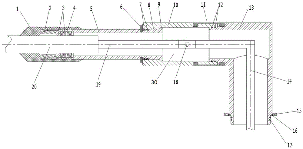
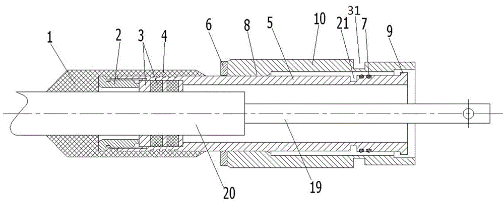
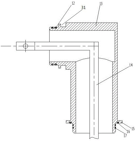
[0022] Examples of electrical connector assemblies are Figure 1~3 Shown: including a first cable, a second cable and an electrical connector, the first cable includes a first cable core 20 and a first connection row 19 connected to the rear end of the first cable core 20, the second cable includes a second connection row 14, the first connecting row 19 and the second connecting row 14 are all copper bars, and the second connecting row 14 is a right-angled L-shaped structure. Through the screw connection holes 18 for the connection of the first connection row and the second connection row, the screw connection holes are waist-shaped holes extending in the front-rear direction. The electrical connector includes a front housing and a rear housing 13. The front housing includes a fixed housing 5 spaced from the rear housing 13 in use. The fixed housing has a first inner hole for the first cable to pass through. The housing 13 has a second inner hole for the second cable to pass through. The rear housing 13 is also a right-angled L-shaped structure. The lower end of the rear housing is provided with a connecting flange 15 for connecting with corresponding equipment. The connecting flange 15 An end face seal ring 16 and a peripheral face seal ring 17 are arranged at the place. Between the fixed housing 5 and the rear housing, there is a connection space 30 for connecting the first connection row of the first cable with the second connection row of the second cable, and the screws on the first connection row 19 and the second connection row 14 The connection hole is located in the connection space 30 . The front housing also includes a shielding sleeve 10 that guides and moves and is sleeved on the fixed housing. The shielding sleeve 10 has an escape position that allows the connection space 30 and a shielding position that blocks the connection space 30 in its moving stroke. The fixed housing 5 The rear end of the housing is provided with a fixed housing sealing ring 7, and the front end of the rear housing 13 is provided with a rear housing sealing ring 12. Through the corresponding sealing cooperation between the fixed housing sealing ring 7, the rear housing sealing ring 12 and the shielding sleeve 10, Guarantee the sealing fit relationship between the shielding sleeve 10 and the fixed housing 5 and the rear housing 13 when the shielding sleeve 10 is in the shielding position, so as to realize the sealing of the joints of the first connecting row and the second connecting row. The inner periphery of the front end of the shielding sleeve 10 is provided with a shielding sleeve inner ring platform 8, and the front and rear sides of the shielding sleeve inner ring platform 8 on the fixed housing 5 are respectively provided with a retaining spring 6 and a fixed housing outer ring platform 9. 6. The cooperation between the outer ring platform 9 of the fixed housing and the inner ring platform 8 of the shielding sleeve limits the position of the front end of the shielding sleeve when the shielding sleeve is in the blocking position; the rear end of the shielding sleeve and the front end of the rear housing are also provided with Corresponding half-connection rings 11 snap-fit ​​into the slots 31 , and the front end of the shielding sleeve is limited when the shielding sleeve is in the shielding position through the buckle of the two plate connecting rings 11 . A stuffing ring 3 is arranged between the front end of the fixed housing 5 and the first core wire of the first cable, and the radial position of the first cable is limited and sealed by the stuffing ring 3 to ensure that the first connection row and the fixed shell The spacing between the bodies, the packing ring is fixed by the fixed nut 2 screwed on the front end of the fixed shell, the fixed nut and the front end of the fixed shell are provided with a connecting groove 4, after the radial position of the first cable is determined, after the fixed A vulcanized sleeve 1 is provided between the casing and the outer periphery of the first cable through a vulcanization process to ensure the sealing and connection strength between the first cable and the fixed casing.
[0023] The assembly process of the electrical connector assembly is as follows: the circlip is taken out from the circlip groove 21 on the fixed housing, and the circlip and the shielding sleeve are retracted together, so as to make room for the connection space such as figure 2 As shown, the first cable core wire of the first cable passes through the fixed housing, and the first cable core wire is connected with the first connecting row. The core wire is sealed, and then vulcanized to form the vulcanized sleeve; the second cable core wire is connected to the second connection row, the rear shell is sealed with the equipment, the first and second connection rows are connected with screws, and the first connection After the row and the second connecting row are connected, push the shielding sleeve backward to the shielding position. At this time, the outer ring platform of the fixed housing and the inner ring platform of the shielding sleeve stop and cooperate to restrict the shielding sleeve from continuing to move forward. In the snap ring groove on the fixed housing, the position limitation to the front end of the shielding sleeve is completed, and the two half-connecting rings are buckled on the shielding sleeve and the rear housing to complete the spacing to the rear end of the shielding sleeve.
[0024] The electrical connector does not need to use contacts to conduct current, and the current is transmitted through the cable itself, which can greatly reduce the size of the electrical connector; the first connecting row and the second connecting row are connected by screws to ensure that the first connecting row It is detachable from the second connecting row, and at the same time can ensure the tensile capacity between the first cable and the second cable; the setting of the shielding sleeve also facilitates the handling of the seal, which can be realized only by using the sealing ring. In other embodiments of the electrical connector: when the first cable and the second cable do not need to be disassembled, the first connecting row and the second connecting row can be directly welded together. Of course, at this time, the first connecting row and the second connecting row It can also be omitted, the first cable core wire of the first cable and the second cable core wire of the second cable can be directly welded together; It may not be the structure of the retaining ring, the outer ring platform of the fixed shell, and the inner ring platform of the shielding sleeve, for example, the top wire that is screwed on the shielding sleeve in the radial direction; the axial movement limit between the shielding sleeve and the rear housing is realized. The rear limit structure of the bit can also not be the structure of the card slot and the semi-connecting ring, for example, the top screw that is screwed radially on the shielding sleeve, or the sleeve connecting nut is rotated on the rear shell, and on the shielding sleeve Set the external thread that cooperates with the connecting nut; Of course, only one front and rear limit structure can be set; When the sealing ring between the rear shells can provide enough friction to limit the position of the shielding sleeve, it is enough to rely on the friction between the sealing ring and the shielding sleeve to limit the position of the shielding sleeve; the shielding sleeve and the fixed shell, the rear shell It is also possible not to seal through the sealing ring. For example, when the processing accuracy is high, the sealing can be directly achieved through the cooperation of the surface and the surface. When the electrical connector is used indoors without waterproofing, the shielding sleeve and the fixed housing , The sealing ring between the rear shells can also not be established.
[0025] Examples of electrical connectors are Figure 1~3 As shown: the specific structure of the electrical connector is the same as that of the electrical connector described in the above-mentioned embodiments of the electrical connector assembly, and will not be described in detail here.
[0026] Examples of front housings are Figure 1~3 As shown: the specific structure of the front housing is the same as the front housing described in the above-mentioned embodiments of the electrical connector assembly, and will not be described in detail here.

PUM

no PUM

Description & Claims & Application Information

We can also present the details of the Description, Claims and Application information to help users get a comprehensive understanding of the technical details of the patent, such as background art, summary of invention, brief description of drawings, description of embodiments, and other original content. On the other hand, users can also determine the specific scope of protection of the technology through the list of claims; as well as understand the changes in the life cycle of the technology with the presentation of the patent timeline. Login to view more.
Why Eureka
Try Eureka