Check patentability & draft patents in minutes with Patsnap Eureka AI!

projector lock

A projection device and projector technology, which is applied to projection devices, supporting machines, mechanical equipment, etc., can solve the problems of inability to sense and identify, the laser screen cannot be covered with projection images, and the projection images cannot be sensed for writing.

Active Publication Date: 2018-02-06
BENQ CORP
View PDF5 Cites 0 Cited by
  • Summary
  • Abstract
  • Description
  • Claims
  • Application Information

AI Technical Summary

Problems solved by technology

After deducting the safety distance of the laser touch module, the laser screen generated by the laser touch module cannot cover the entire projection screen
In other words, with the configuration of the existing laser touch module, some positions of the projected screen cannot sense the writing action
In this way, when the user writes on the projection screen, it may not be recognized by induction
Therefore, the existing projection device combined with the laser touch module still needs to be improved.

Method used


Image

  • projector lock
  • projector lock
  • projector lock

Examples


Embodiment Construction

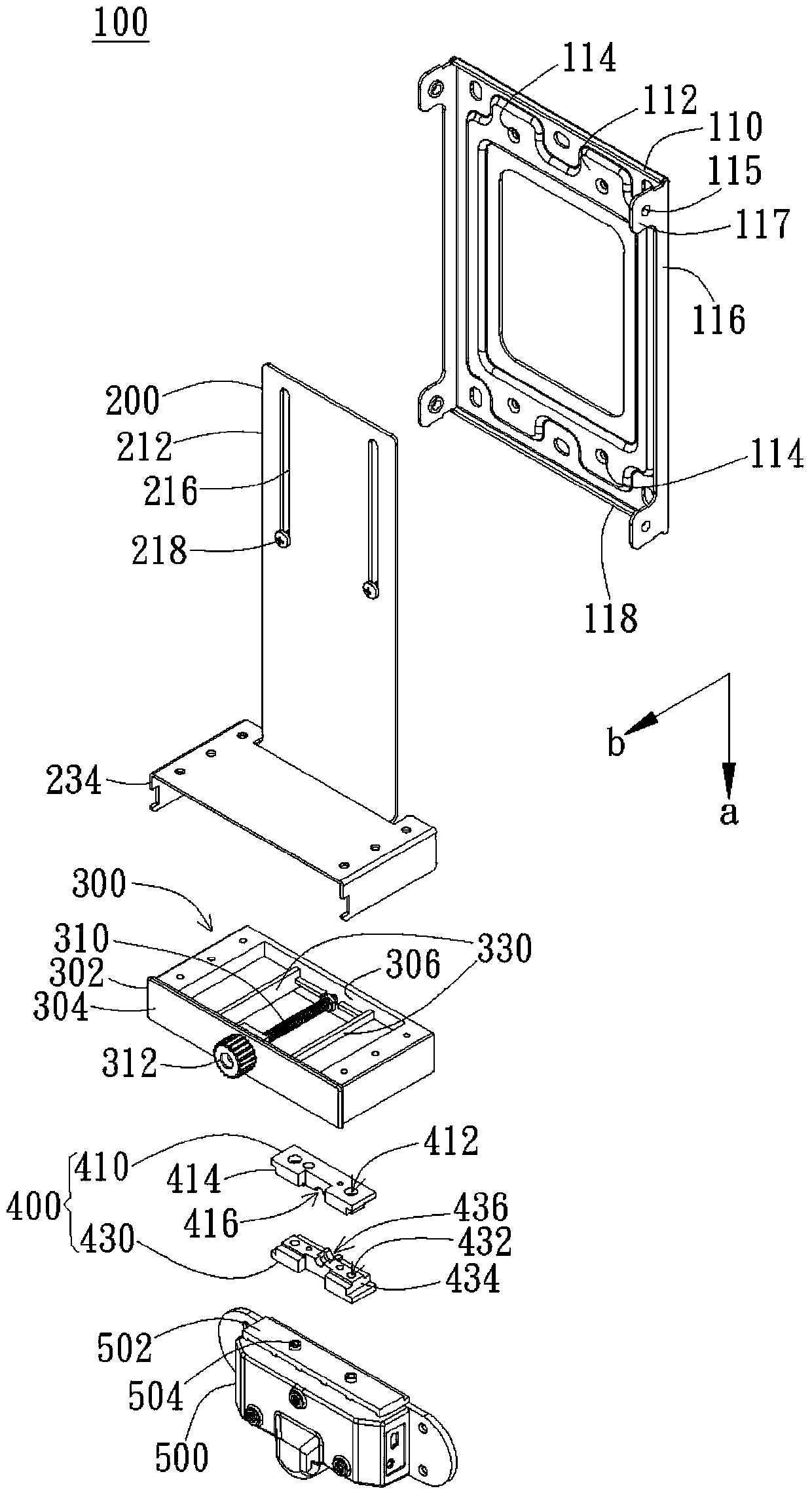
[0070] The projector locking device of the present invention is used to adjust the position of the laser light source on the installation surface, so that the range of the laser screen can match the size of the projection screen and cover the projection screen. Please refer to the specific structure figure 1 .

[0071] figure 1 It is an exploded view of an embodiment of the projector locking device 100 of the present invention. Such as figure 1 As shown, the projector locking device 100 includes a main frame body 110 , a connecting body 200 , a telescoping adjustment device 300 , a moving part 400 and a detection module 500 . The main frame body 110 can be installed on the installation surface. Specifically, the main frame body 110 has a back plate 112 , and side plates 116 are connected to both sides of the back plate 112 along the extending direction a of the connecting body 200 . A plurality of first locking holes 114 are opened on the back plate 112 for combining the ...


PUM


Abstract

The projector locking device of the present invention includes a main frame body, a connecting body, a telescopic adjustment device and a projection device bracket. The main frame is used to be fixed on the setting surface. One end of the connecting body is connected to the main frame. The telescopic adjusting device is fixed on the other end of the connecting body opposite to the main frame along the extending direction of the connecting body. There is a moving part in the telescoping adjustment device, which is arranged to move along a first direction perpendicular to the extension direction of the connecting body, and the moving part is used to connect with the detection module. The first end of the projection device support is connected to the main frame, and the projection device support has a second end facing away from the setting surface and extending along the first direction, and the second end is used for connecting the projector.

Description

technical field [0001] The invention relates to a projector locking device; specifically, the invention relates to a projector locking device capable of adjusting the position of a laser light source along with the installation surface. Background technique [0002] Projection devices have the advantage of outputting large-size images. With the technological advancement of display quality, projection devices have been widely used in conference rooms, exhibition venues, and school classrooms. At present, there are products that combine a projection device with a laser touch module, allowing users to directly input and write on the projection screen. Specifically, this technology uses the laser light emitted by the laser touch module to form a laser screen, which covers the projection screen. When an object touches the screen, it will reflect the laser light, and then the relative position will be identified by the lens of the projector, so as to achieve the operation method ...

Claims


Application Information

Patent Timeline
Patent Type & Authority Patents(China)
IPC IPC(8): G03B21/20G03B21/14
CPCG03B21/145G03B21/26F16M11/048F16M11/18F16M11/24F16M13/02G06F3/0421F16B7/1472
Inventor 张嘉麟叶千榆
Owner BENQ CORP
Features
  • R&D
  • Intellectual Property
  • Life Sciences
  • Materials
  • Tech Scout
  • Unparalleled Data Quality
  • Higher Quality Content
  • 60% Fewer Hallucinations
Learn More