Current continuous high-gain switch voltage rise quasi-Z-source converter circuit

A switching boost, continuous technology, applied in the direction of converting DC power input to DC power output, adjusting electrical variables, and converting equipment without intermediate conversion to AC, which can solve the problem of different output and input, and a large start-up shock Current, power supply current discontinuity and other problems, to achieve the effect of good starting inrush current, high gain, and improved reliability

A switching boost, continuous technology, applied in the direction of converting DC power input to DC power output, adjusting electrical variables, and converting equipment without intermediate conversion to AC, which can solve the problem of different output and input, and a large start-up shock Current, power supply current discontinuity and other problems, to achieve the effect of good starting inrush current, high gain, and improved reliability

CN105958823AActive Publication Date: 2016-09-21DONGGUAN SHILONG FUHUA ELECTRONICS

Image

  • Current continuous high-gain switch voltage rise quasi-Z-source converter circuit
  • Current continuous high-gain switch voltage rise quasi-Z-source converter circuit
  • Current continuous high-gain switch voltage rise quasi-Z-source converter circuit

Examples


Embodiment Construction

[0011] The technical solution of the present invention has been described in detail above, and the specific implementation of the present invention will be further described below in conjunction with the accompanying drawings.

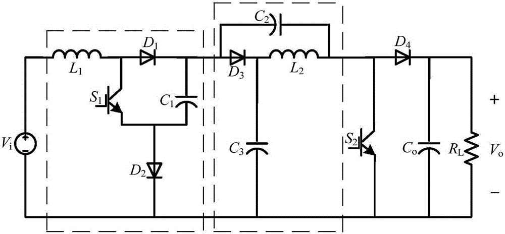
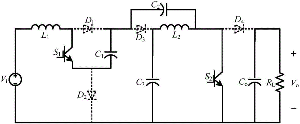
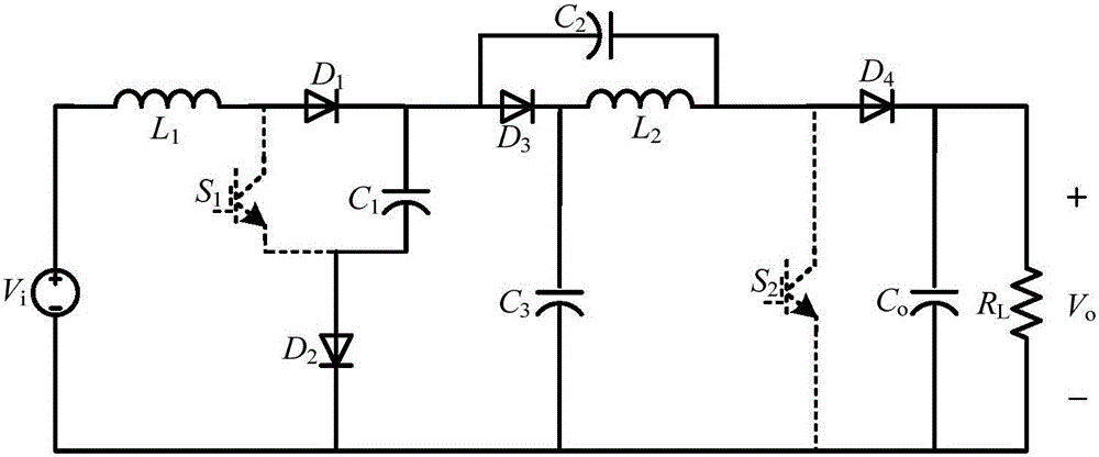
[0012] refer to figure 1 , a current continuous type high-gain switch step-up quasi-Z source converter circuit according to the present invention, which includes a voltage source V i , by the first inductance L 1 , the first diode D 1 , the first capacitance C 1 , the first switching tube S 1 and the second diode D 2 constitutes a switching boost unit and consists of a second inductor L 2 , the second capacitance C 2 , the third capacitor C 3 and the third diode D 3 A quasi-Z source network consisting of a fourth diode D 4 , the second switch tube S 2 , the output capacitance C o and load R L . When the first switch S 1 and the second switch tube S 2 While conducting, the first diode D 1 , the second diode D 2 , the third diode D 3 an...


PUM


Abstract

The invention provides a current continuous high-gain switch voltage rise quasi-Z-source converter circuit. The circuit comprises a power supply; a two-port switch voltage rise unit composed of a first inductor, a first diode, a first power switch tube, a first capacitor and a second diode; a quasi-Z-source network composed of a second inductor, a second capacitor, a third capacitor and a third diode; a second power switch tube; a fourth diode; an output capacitor; and a load. The whole circuit is simple in structure; the single-level voltage rise and reduction features of the switch voltage rise unit and the quasi-Z-source network are combined; the higher output voltage gain is realized; the current of the power supply is continuous; the current of the load is continuous; the output and input are in zero potential; there is no start surge current in the circuit; and there is no surge current at the moment when the switch tube is switched on.

Description

technical field [0001] The invention relates to the technical field of power electronic circuits, in particular to a current continuous high-gain switch boost quasi-Z source converter circuit. Background technique [0002] In fuel cell power generation and photovoltaic power generation, due to the low DC voltage provided by a single solar cell or a single fuel cell, it cannot meet the electricity demand of existing electrical equipment, nor can it meet the needs of grid connection. It is often necessary to combine multiple batteries connected in series to achieve the desired voltage. On the one hand, this method greatly reduces the reliability of the entire system, and on the other hand, it needs to solve the problem of series voltage equalization. For this reason, a high-gain converter circuit capable of converting a low voltage to a high voltage is required. The Z-source boost converter proposed in recent years is a high-gain converter circuit, but the circuit has a high...

Claims


Application Information

Patent Timeline
21 Sep 2016
Publication
CN105958823A
IPC
H02M3/156; H02M3/07
CPC
H02M3/07; H02M3/156
Inventors
张波; 朱小全