High-gain DC voltage boost conversion circuit

A technology for transforming circuits and DC voltages, applied in the direction of converting DC power input into DC power output, adjusting electrical variables, electrical components, etc., which can solve the disadvantages of power generation systems from making full use of environmental energy, application limitations of Boost conversion circuits, and low output voltage of photovoltaic cells etc. to achieve the effect of convenient control, high output voltage gain, and simple circuit structure

Active Publication Date: 2018-09-21
东台城东科技创业园管理有限公司
View PDF3 Cites 0 Cited by
  • Summary
  • Abstract
  • Description
  • Claims
  • Application Information

AI Technical Summary

Problems solved by technology

[0005] The most typical DC step-up conversion is the Boost conversion circuit. Considering the actual parameters of the boost conversion circuit, its boost ratio is not large, and it can still meet the basic boost requirements when used in a direct-drive wind power generation system. In the system, due to the low output voltage of the photovoltaic cell, the application of the Boost conversion circuit is limited, which is not good for the power generation system to fully utilize the environmental energy. Configuring a multi-stage boost conversion circuit will affect the efficiency of the entire system, and a high-gain boost conversion circuit needs to be configured.

Method used


Image

  • High-gain DC voltage boost conversion circuit
  • High-gain DC voltage boost conversion circuit
  • High-gain DC voltage boost conversion circuit

Examples


Embodiment Construction

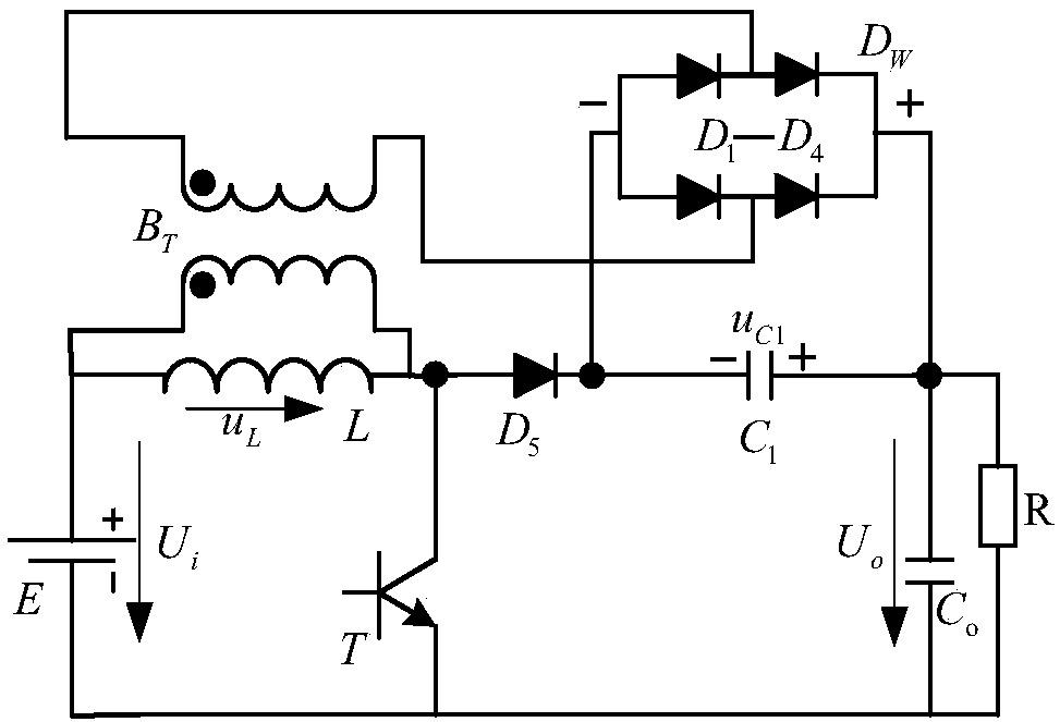
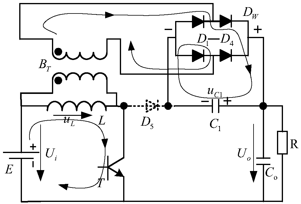
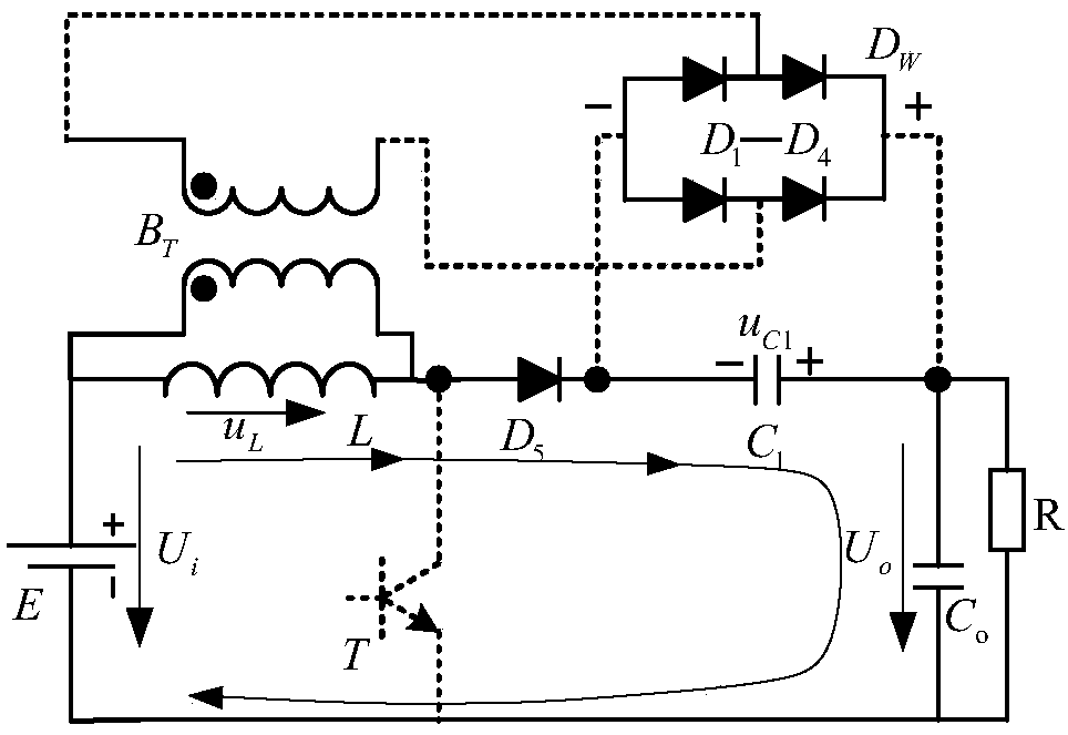
[0040] The present invention will be further described below in conjunction with the accompanying drawings and specific embodiments.

[0041] Figure 1-5 Among them, E is the input power supply, L is the inductance of the conversion circuit, B T It is a high-frequency transformer for the conversion circuit. The "·" terminal of the primary side and secondary winding of the transformer is the terminal with the same name, and C 1 is the conversion circuit capacitance, C o Output filter capacitor for the conversion circuit, D 1 -D 4 In order to transform the rectifier bridge connected to the secondary side of the high-frequency transformer of the circuit, for the convenience of explanation, the rectifier bridge composed of these four diodes is regarded as a whole D W , bridge rectifier D W The two AC input ends are marked as ":" port, D W The DC output terminals are marked as "+" terminal and "-" terminal respectively, D 5 is the boost diode of the conversion circuit, T is ...


PUM


Abstract

The invention discloses a high-gain DC voltage boost transformation circuit and belongs to the technical field of a power transformation circuit. The anode of E is connected with one end of L and one end of a BT primary winding; the cathode of E is connected with a switch tube emitter electrode, a low-potential end of Co and a low-potential end of R; the other end of L is connected with a switch tube collector electrode, the other end of the BT primary winding and the anode of D5; the cathode of D5 is connected with a low-potential end of a capacitor C1 and a negative end of a rectifier DW; a high-potential end of C1 is connected with a high-potential end of Co, a high-potential end of R and a positive end of the DW; and the two ends of a BT secondary winding are connected with two AC input ends of DW. According to the invention, pump voltages of an inductance element are connected in series with capacitance voltages charged by a rectified high-frequency transformer secondary winding excited by AC voltages at the two sides of the inductor according to polarity for supplying power to a load, input AC voltages are boosted, boost transformation control of the DC voltages is implemented, and obtained output voltage gains are much more than that of a single-stage boost chopper transformation circuit.

Description

technical field [0001] The invention belongs to the technical field of power conversion circuits, and in particular relates to a high-gain DC voltage boost conversion circuit. Background technique [0002] At present, with social development and technological progress, global energy tensions are intensifying. The use of fossil energy has had an extremely bad negative impact on the living environment of human beings. The natural crisis caused by air and water pollution is shocking. Therefore, , Renewable energy power generation systems such as wind energy and solar energy are being widely accepted by the whole society and promoted and applied. [0003] However, in the process of development and application of wind energy and solar energy, due to the influence of wind speed, sunlight, climate and other factors, the randomness of wind energy and solar energy and other renewable energy generation systems makes the large-scale application of these renewable energy sources greatly...

Claims


Application Information

Patent Timeline
Patent Type & Authority Patents(China)
IPC IPC(8): H02M3/335
CPCH02M3/33523
Inventor 陈荣顾春雷杨晓冬陈中王银杰白雪飞
Owner 东台城东科技创业园管理有限公司
Why Eureka
Try Eureka