
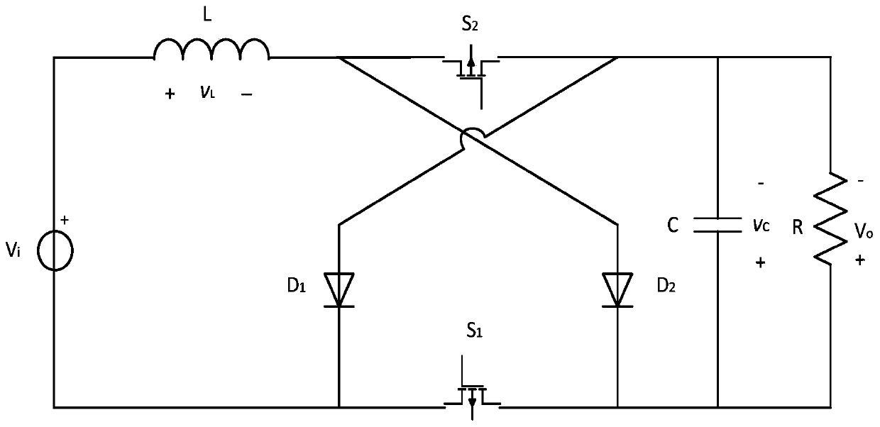
A kind of dual-transistor z-source DC voltage converter

A DC voltage and converter technology, which is applied in the direction of converting DC power input to DC power output, adjusting electrical variables, instruments, etc., and can solve problems such as excessive peak current of switching tubes and diodes, discontinuous input current, and large output voltage. , to achieve the effect of high output voltage gain, continuous input current and convenient control mode

Active Publication Date: 2019-12-10
SOUTH CHINA UNIV OF TECH
View PDF3 Cites 0 Cited by
  • Summary
  • Abstract
  • Description
  • Claims
  • Application Information

AI Technical Summary

Problems solved by technology

The Z-source converter proposed in recent years achieves a large output voltage at a low duty cycle, and overcomes the defects of the boost converter such as excessive peak current of the switch tube and diode caused by the limit duty cycle.
However, the input current of the traditional Z-source converter is discontinuous, which is not conducive to input side filtering. At the same time, the Z-source converter uses two capacitors and two inductors, which is not conducive to reducing the volume of the system and improving the power density of the system.

Method used


Image

  • A kind of dual-transistor z-source DC voltage converter
  • A kind of dual-transistor z-source DC voltage converter
  • A kind of dual-transistor z-source DC voltage converter

Examples


Embodiment Construction

[0011] The present invention will be further described below in conjunction with specific examples.

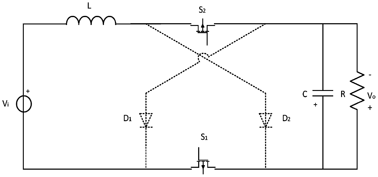
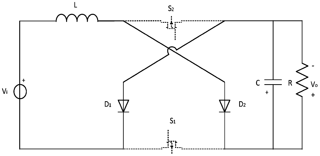
[0012] see figure 1 As shown, the dual-transistor Z-source DC voltage converter provided in this embodiment includes a voltage source V i , inductance L, capacitance C, first switching tube S 1 , the second switch tube S 2 , the first diode D 1 , the second diode D 2 and load R; the voltage source V i The positive pole of the inductor L is connected to one end of the inductor L, and its negative pole is respectively connected to the first switching tube S 1 source and the first diode D 1 The cathode connection; the first switching tube S 1 The drains are connected to the second diode D 2 The cathode of the capacitor C is connected to one end of the load R; the second switch tube S 2 The drains are connected to the second diode D 2 The anode of the inductance L is connected to the other end; the second switching tube S 2 The sources are respectively connected to the ...


PUM


Abstract

The invention discloses a double-pipe Z-source direct-current voltage converter. The converter comprises a voltage source, an inductor, a capacitor, a first switch tube, a second switch tube, a first diode, a second diode and a load. The positive electrode of the voltage source is connected with one end of the inductor, and the negative electrode is connected with the source electrode of the first switch tube and the cathode of the first diode. The drain electrode of the first switch tube is connected with the cathode of the second diode, the positive electrode of the capacitor and one end of the load. The drain electrode of the second switch tube is connected with the anode of the first diode, the negative electrode of the capacitor and the other end of the load. The converter is simple in structure and convenient to control, input current is continuous, quite high output voltage gain under the low duty ratio can be achieved and the circuit is free from a start impacting problem.

Description

technical field [0001] The invention relates to the technical field of power electronic converters, in particular to a dual-tube Z-source DC voltage converter. Background technique [0002] With the rapid development of industrial production, high-power, high-gain converters are playing an increasingly important role in occasions that require power conversion. The Z-source converter proposed in recent years achieves a large output voltage at a low duty cycle, and overcomes the defects of the boost converter such as the excessive peak current of the switch tube and diode caused by the limit duty cycle. However, the input current of the traditional Z-source converter is discontinuous, which is not conducive to input side filtering. At the same time, the Z-source converter uses two capacitors and two inductors, which is not conducive to reducing the volume of the system and improving the power density of the system. Contents of the invention [0003] The purpose of the prese...

Claims


Application Information

Patent Timeline
Patent Type & Authority Patents(China)
IPC IPC(8): H02M3/158
CPCH02M3/158
Inventor 陈艳峰陈柱张波丘东元
Owner SOUTH CHINA UNIV OF TECH
Learn More