

An Improved Main Shaft Locking Device and Its Application
A technology of locking device and main rotating shaft, applied in the field of locking devices, can solve problems such as slow lifting, damage to transported objects, etc.
- Summary
- Abstract
- Description
- Claims
- Application Information
AI Technical Summary
Problems solved by technology
Method used
Image

Examples
Embodiment Construction
[0031] Taking the specific application of the main shaft locking device in the driving device of the lifting handcart as an example, the utility model will be described in detail in conjunction with the accompanying drawings.
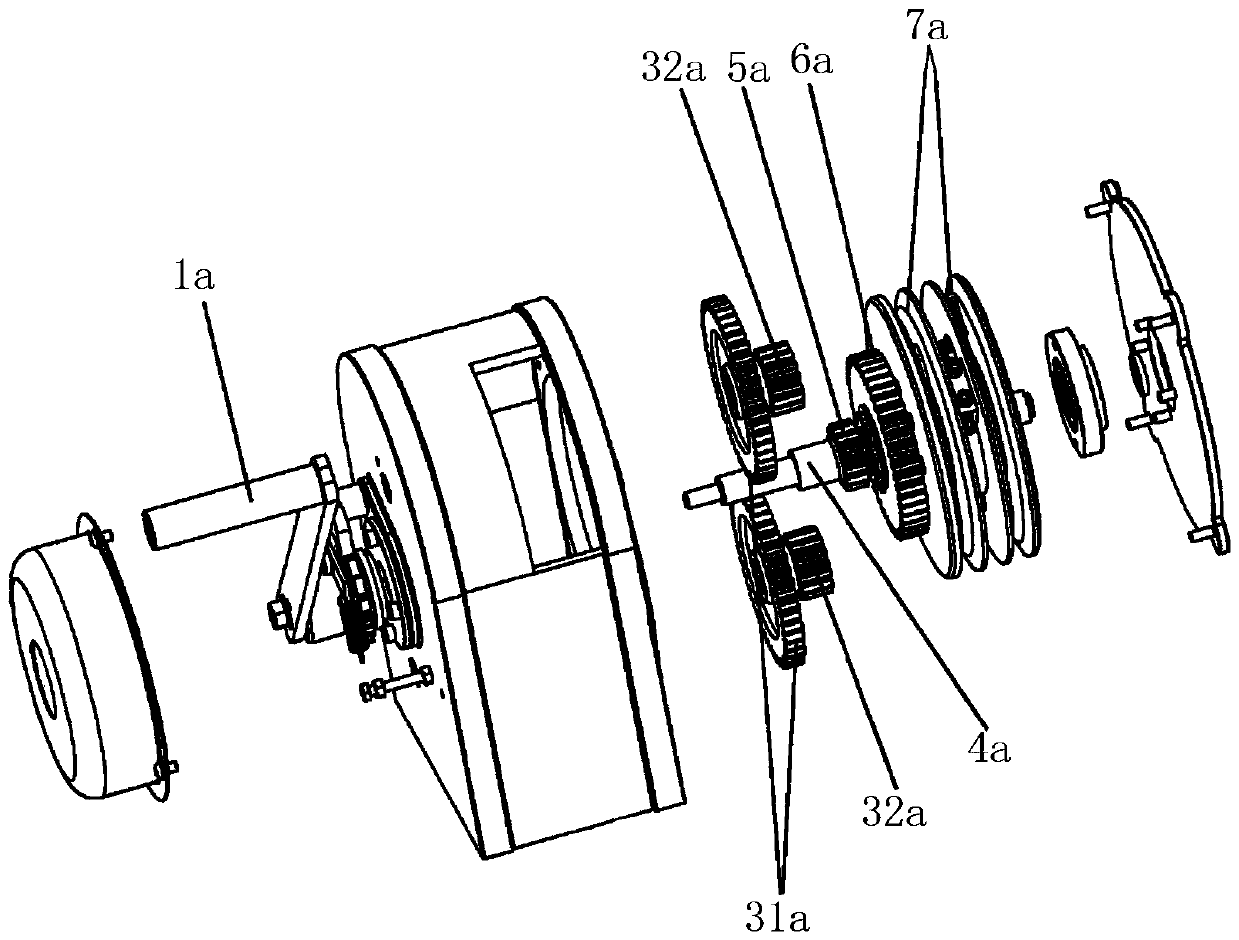
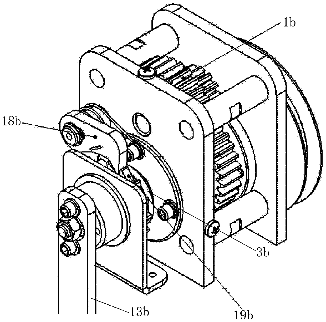
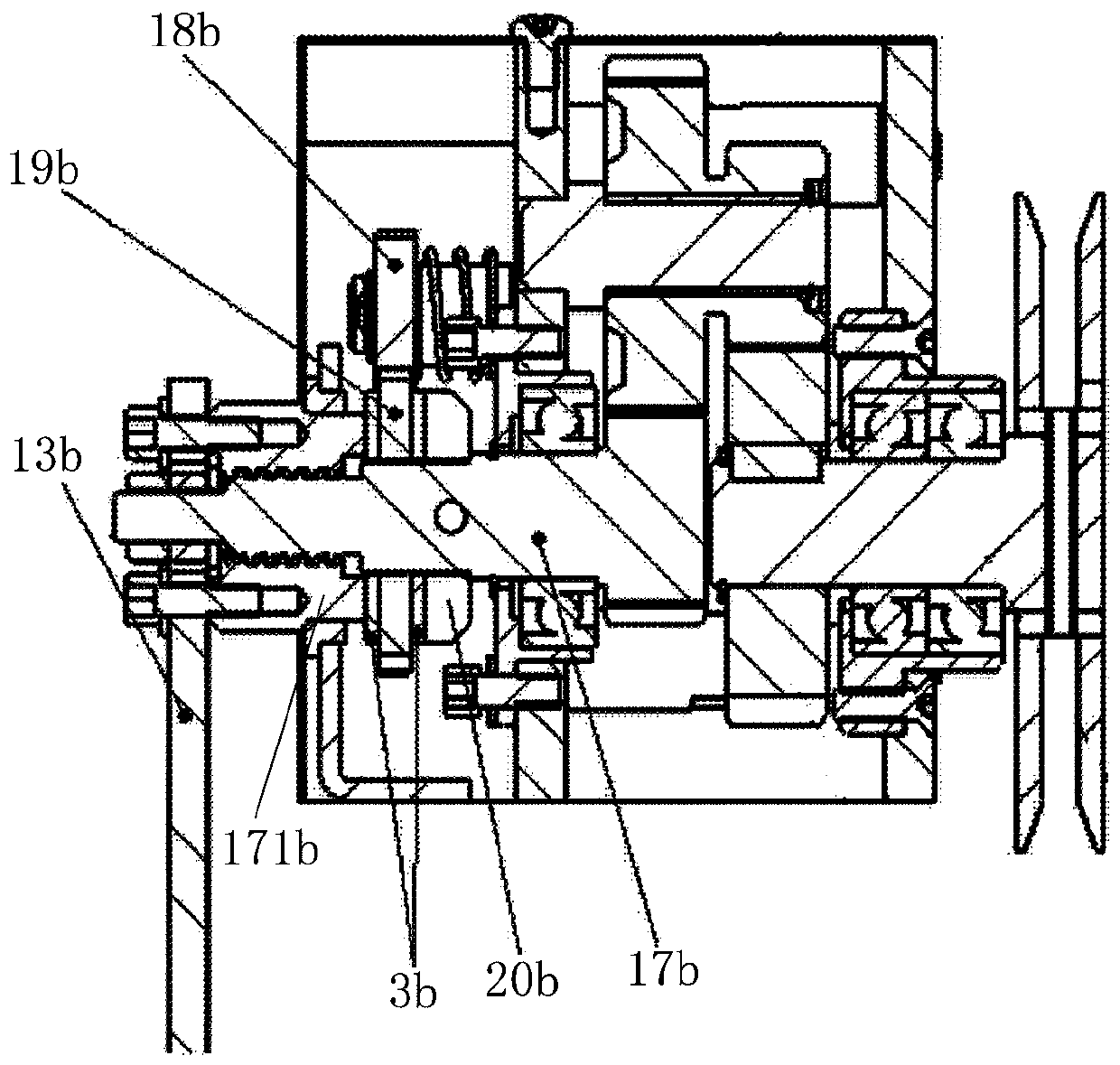
[0032] Such as image 3 , 4 , 5-1, 5-2 shown, a kind of improved lifting handcart power driving device, it comprises reduction gear box 1 and handle 2, and described reduction gear box 1 comprises chassis 10, reduction gear set, main shaft 11. External ratchet 12, ratchet 13, anti-rotation disk 14, first brake pad 15, second brake pad 16, connecting nut 17 and wire wheel 100; The large teeth on the main rotating shaft 11 are meshed with the small teeth to form (see figure 1 ), to achieve the purpose of deceleration; or as shown in Figures 5 and 6, a gear 111 is provided on the main shaft 11, the gear 111 meshes with the secondary reduction gear 112, and the small tooth end of the secondary reduction gear 112 is then connected to the The output gears ...
PUM
 Abstract
Description
Claims
Application Information