body reinforcement structure

A technology for strengthening the structure and the body, applied in the directions of the substructure, the superstructure, the subassembly of the superstructure, etc., can solve the problem of inability to input load transmission, etc., and achieve the effect of improving the load transmission performance

Inactive Publication Date: 2018-01-09
TOYOTA JIDOSHA KK
View PDF8 Cites 0 Cited by
  • Summary
  • Abstract
  • Description
  • Claims
  • Application Information

AI Technical Summary

Problems solved by technology

However, in such a structure, when an input load such as a collision occurs, the input load cannot be effectively transmitted to the reinforcing plate member unless the reinforcing plate member conforms to the deformation of the metal plate.

Method used


Image

  • body reinforcement structure
  • body reinforcement structure
  • body reinforcement structure

Examples


no. 1 approach

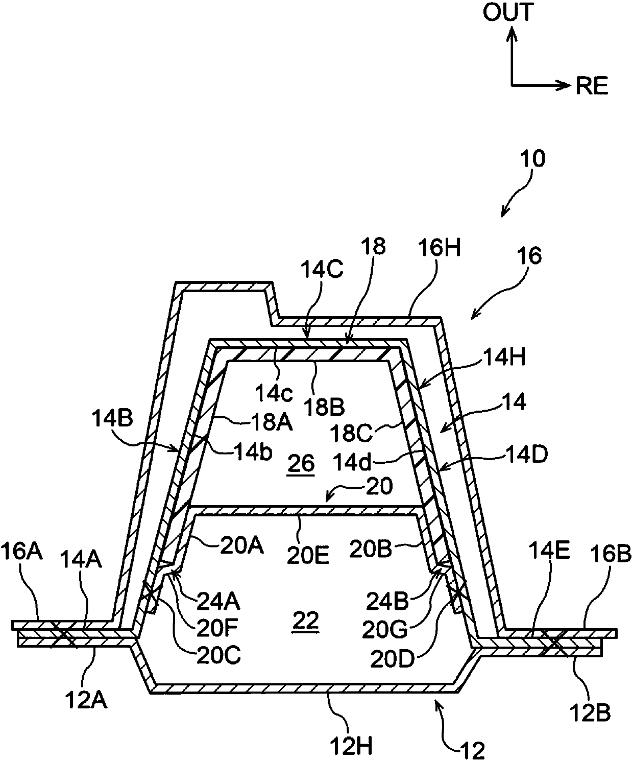
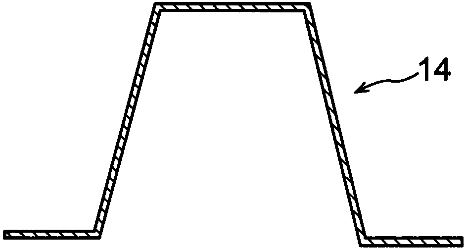
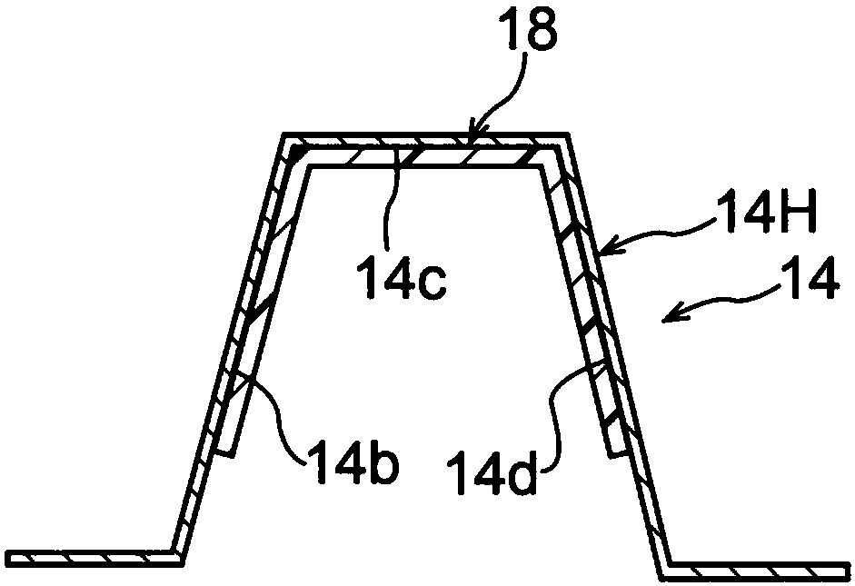
[0037] use Figure 1 to Figure 4 , the vehicle body reinforcement structure according to the first embodiment of the present invention will be described. In addition, in figure 1In , arrow RE indicates the vehicle rear side, and arrow OUT indicates the vehicle width direction outer side.

[0038] figure 1 The center pillar 10 to which the vehicle body reinforcement structure according to this embodiment is applied is illustrated in a horizontal cross-sectional view. As shown in the figure, the center pillar 10 includes a metal (in this embodiment, steel) inner panel 12 constituting its inner portion in the vehicle width direction. The inner panel 12 is formed in a top hat shape that opens outward in the vehicle width direction when viewed in horizontal cross-section, and includes a substantially U-shaped main body portion 12H that opens outward in the vehicle width direction when viewed in horizontal cross-section. A front flange portion 12A is formed to bend and extend to...

no. 2 approach

[0069] Next, use Figure 5 Next, a vehicle body reinforcement structure according to a second embodiment of the present invention will be described. Figure 5 12 is a horizontal cross-sectional view of the center pillar 30 to which the vehicle body reinforcement structure according to the present embodiment is applied (corresponding to that of the first embodiment). figure 1 diagram). As shown in the figure, in the center pillar 30, the second reinforcing member 32 as the second reinforcing member arranged to prevent the first reinforcing member 18 from falling off has a connecting portion 34 instead of the connecting portion 20E( figure 1 Reference), this point is related to the center pillar 10 ( figure 1 Reference) is different. The other structures are the same as those of the first embodiment. Therefore, the same reference numerals are assigned to the same constituent parts as those in the first embodiment, and description thereof will be omitted.

[0070] Such as ...

no. 3 approach

[0077] Next, use Figure 6 Next, a vehicle body reinforcement structure according to a third embodiment of the present invention will be described. Figure 6 Horizontal sectional view for middle use (equivalent to that of the first embodiment figure 1 ) shows a center pillar 40 to which the vehicle body reinforcement structure according to the present embodiment is applied. As shown in the figure, in the center pillar 40, the structure of the second reinforcement reinforcement 42 as the second reinforcement member on the outer side in the vehicle width direction has the same structure as that of the second reinforcement reinforcement 20 ( figure 1 The structure of the part outside in the vehicle width direction in reference) is different. The other structures are the same as those of the first embodiment. Therefore, the same reference numerals are assigned to the same constituent parts as those in the first embodiment, and description thereof will be omitted.

[0078] Such...


PUM


Abstract

It is provided a vehicle body reinforcing structure that can effectively transmit input load to a reinforcing member formed of a fiber reinforced resin material, in a case in which load is inputted to a vehicle body structural member that is made of metal. A first reinforcing reinforcement (18) that is formed of a fiber reinforced resin material is continuously superposed with and adhered to an inner wall surface (14b) of a front wall portion (14B), an inner wall surface (14c) of an outer wall portion (14C), and an inner wall surface (14d) of a rear wall portion (14D) of an outer reinforcement (14). A pair of superposed portions (20A, 20B) of a second reinforcing reinforcement (20) are superposed, via the first reinforcing reinforcement (18), with the inner wall surface (14b) of the front wall portion (14B) and the inner wall surface (14d) of the rear wall portion (14D) of the outer reinforcement (14). The second reinforcing reinforcement (20) is directly joined to the front wall portion (14B) and the rear wall portion (14D) of the outer reinforcement (14), and the pair of superposed portions (20A, 20B) are connected by a connecting portion (20E).

Description

technical field [0001] The invention relates to a vehicle body reinforcement structure. Background technique [0002] In vehicles, in order to reduce the weight of the vehicle body, a panel member made of a fiber-reinforced resin material is sometimes bonded to a metal plate (for example, refer to Patent Document 1). [0003] prior art literature [0004] patent documents [0005] Patent Document 1: Japanese Patent Application Laid-Open No. 2009-35045 [0006] The problem to be solved by the invention [0007] However, there are cases where a panel member formed of a fiber-reinforced resin material is bonded to a metal panel constituting a part of a vehicle body for reinforcement. However, in such a structure, when an input load such as a collision occurs, the input load cannot be efficiently transmitted to the reinforcing plate member unless the reinforcing plate member conforms to the deformation of the metal plate. [0008] In consideration of the above facts, an obj...

Claims


Application Information

Patent Timeline
Patent Type & Authority Patents(China)
IPC IPC(8): B62D25/04B62D25/20
CPCB62D25/025B62D25/04B62D29/005B62D21/15B62D24/00
Inventor 稻本好辉
Owner TOYOTA JIDOSHA KK
Why Eureka
Try Eureka