
An electric bicycle performance testing platform

An electric bicycle and test platform technology, which is applied in vehicle testing, machine/structural component testing, measuring devices, etc., can solve the problem of car body loading, unable to quantitatively test the performance of bicycles/light electric motorcycles, and unable to quantitatively simulate the car body Affected by the problems of different resistance states, etc., to achieve the effect of reliable detection results

Active Publication Date: 2018-07-24
天津铭志成科技有限责任公司
View PDF5 Cites 3 Cited by
  • Summary
  • Abstract
  • Description
  • Claims
  • Application Information

AI Technical Summary

Problems solved by technology

[0003] Because electric bicycle / portable electric motorcycle performance testing platform itself has many and bigger frictional forces, and there is frictional resistance between the electric vehicle wheel and the rolling wheel of testing platform (the frictional resistance between the wheel and the rolling wheel of testing platform increases with Tire pattern, tire width, and tire inflation are different), so when using the test platform to test electric vehicles, electric vehicles need to overcome the above uncertain resistance to run, which will cause inaccurate test results.
[0004] At the same time, in the prior art, the test platform cannot quantitatively simulate the state of the car body subject to different resistances (the frictional force of the test platform itself and the friction resistance between the wheels and the rollers of the test platform are uncertain, so the test platform cannot load quantitative resistance on the car body), making it impossible to quantitatively test the performance of bicycles / mopeds under different resistances

Method used


Image

  • An electric bicycle performance testing platform
  • An electric bicycle performance testing platform
  • An electric bicycle performance testing platform

Examples


Embodiment Construction

[0024] The technical solutions of the present invention are further described below in conjunction with specific embodiments.

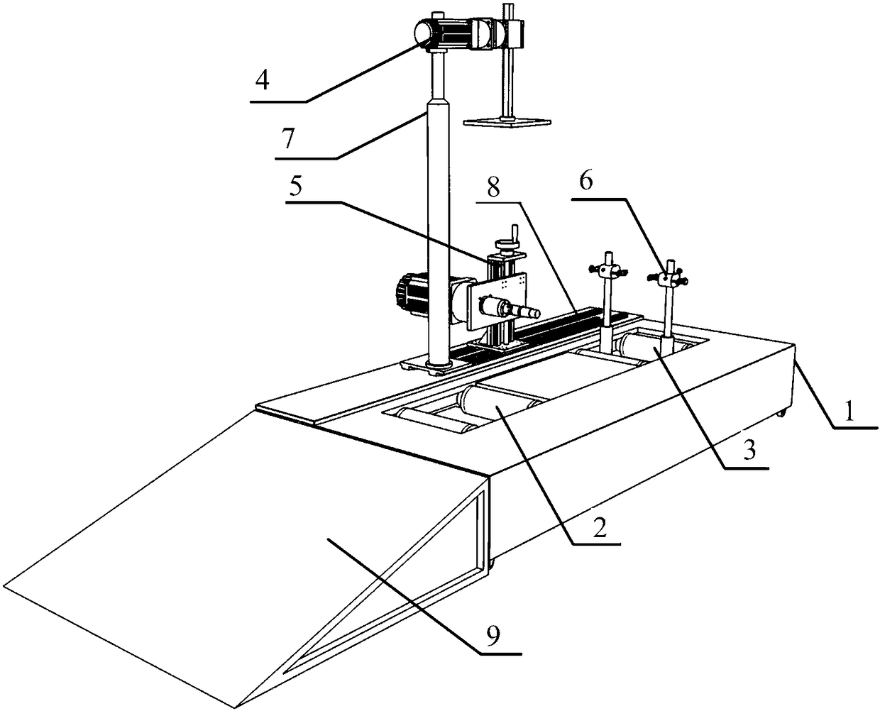
[0025] An electric bicycle performance test platform, see attached figure 1 , including a rear wheel drive device 2 , a front wheel support device 3 , a seat pressing device 4 , a central axle drive device 5 , a front wheel fixing frame 6 , a base frame 10 and a housing 1 .

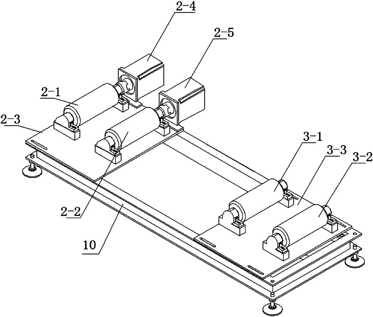
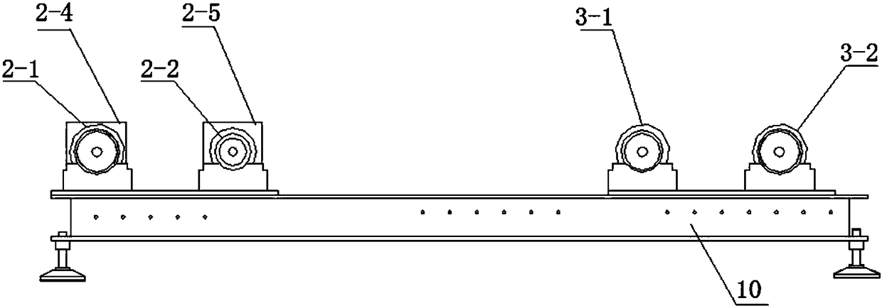
[0026] see attached figure 2 and attached image 3 , the rear wheel drive device 2 includes a first rear axle roller 2-1 and a second rear axle roller 2-2, the first rear axle roller 2-1 and the second rear axle roller 2-2 are parallel to each other through the bearing seat It is arranged on the first flat plate 2-3, and the first flat plate 2-3 is horizontally fixed on the second half of the base frame 10; the first rear axle roller 2-1 is connected with the first motor 2-4; The second rear axle roller 2-2 is connected with the second motor 2-5;

[0027] The front wheel sup...


PUM


Abstract

The invention discloses an electric bicycle performance test platform comprising a rear wheel driving device and a vehicle seat compressing device. The wheel driving device comprises a first rear axle roller and a second rear axle roller. The first rear axle roller and the second rear axle roller are fixed in a mutually parallel way through bearing pedestals. The first rear axle roller is connected with a first motor. The second rear axle roller is connected with a second motor. The rear wheel of a tested vehicle body is arranged in the two rear axle rollers of the rear wheel driving device. The vehicle seat compressing device is used for loading compressing force for the tested vehicle body so as to simulate vehicle-mounted weight. The second motor and the second rear axle roller load positive torque to the rear wheel of the vehicle body to apply push force and the vehicle wheel is enabled to be in the critical operation state so as to compensate frictional force of the test platform and frictional resistance between the vehicle wheel of the electric vehicle and the rollers of the test platform. The first motor and the first rear axle roller load opposite torque to the rear wheel to apply resistance so as to quantitatively simulate the resistance in driving of the electric vehicle.

Description

technical field [0001] The invention belongs to the technical field of testing electric bicycles, and in particular relates to a performance testing platform for electric bicycles. Background technique [0002] The bicycle / moped electric motorcycle performance test platform is a kind of equipment for testing the bicycle / moped electric motorcycle. During the test, the bicycle / moped electric motorcycle is placed on the rollers of the test platform to simulate the riding state on the road to test the electric vehicle. Various performances under riding conditions. [0003] Due to the existence of many and large frictional forces in the performance test platform of electric bicycles / mopeds, and the frictional resistance between the wheels of the electric vehicle and the rollers of the test platform (the frictional resistance between the wheels and the rollers of the test platform increases with the The tire pattern, tire width, and tire inflation are different), so when using th...

Claims


Application Information

Patent Timeline
Patent Type & Authority Patents(China)
IPC IPC(8): G01M17/007
CPCG01M17/007
Inventor 仝燕敏展毓湜
Owner 天津铭志成科技有限责任公司
Learn More