Screen body magnetic vibration air conditioning type drying device

A drying device and magnetic technology, used in air conditioning systems, heating devices, drying solid materials, etc., can solve the problems of reduced drying efficiency, loss of heat energy, low heat energy conversion efficiency, etc., to reduce drying energy consumption, promote heating and drying, energy Loss reduction effect

Inactive Publication Date: 2016-11-09
湘西银湘农业科技有限责任公司 +1
View PDF6 Cites 0 Cited by
  • Summary
  • Abstract
  • Description
  • Claims
  • Application Information

AI Technical Summary

Problems solved by technology

The drying process is essentially the process of discharging the moisture in the material. However, almost all existing drying equipment uses direct heating to discharge the moisture in the material in the form of gaseous water. Because the enthalpy of gaseous water is much higher than that of liquid water And the temperature is high, so a large amount of energy is also discharged when the gaseous water is discharged, which inevitably causes a large amount of heat energy loss, which is obviously not in line with my country's current energy-saving and emission-reduction policies
[0003] Secondly, most of the heating methods of existing drying equipment are direct heating, that is, direct heating by steam or electricity or heat transfer oil, but the thermal conversion efficiency of direct heating is low, and the thermal conversion rate of large boilers can only reach 90% The energy efficiency of heat pump heat transfer is relatively high, which can reach more than 3, which greatly improves the efficiency of heat energy utilization and realizes energy saving and emission reduction.
[0004] Thirdly, some materials are easy to harden during the drying process, which will hinder the evaporation of water and reduce the drying efficiency

Method used


Image

  • Screen body magnetic vibration air conditioning type drying device

Examples


Embodiment Construction

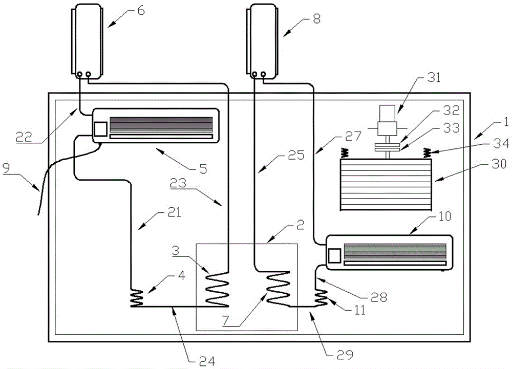
[0022] Now in conjunction with accompanying drawing, the present invention is described in further detail.

[0023] like figure 1 The sieve body magnetic vibration air-conditioning drying device shown in the figure is isolated from the external environment by the thermal insulation enclosure 1, and the thermal insulation enclosure 1 constitutes a dry working environment, in which there is a water tank 2, and the water tank 2 is provided with a spiral coil A3, a spiral coil Pipe B7 and inject an appropriate amount of water to submerge the spiral coil; compressor A6, spiral coil A3, capillary tube A4, refrigeration and air-conditioning internal unit 5, and pipelines 21, 22, 23, and 24 constitute a group A heat pump cycle dehumidification system, in which compressor A6 passes through The pipe 23 is connected to the spiral coil A3, and the spiral coil A3 is connected to the capillary A4 through the pipe 24, and the capillary A4 is connected to the refrigerating and air-conditionin...


PUM


Abstract

The invention discloses a screen body magnetic vibration air conditioning type drying device. A water tank is arranged in a heat insulation enclosure. Water is poured into the water tank to immerse a spiral coil A and a spiral coil B which are located in the water tank. A heat pump circulating dehumidifying system A is formed by a compressor A, the spiral coil A, a capillary tube A, a refrigerating air conditioning internal machine and relevant pipelines. A heat pump circulating heating system B is formed by a heating air conditioning external machine, a heating air conditioning internal machine, a capillary tube B, the spiral coil B and relevant pipelines. Evaporation, condensation and discharge of moisture of materials in the heat insulation enclosure and storage and utilization of heat in the water tank are achieved through alternate working of the system A and the system B. A device used for driving a screen body to conduct differential and impulse type vibration in a magnetic mode is further arranged in the heat insulation enclosure. Compared with an existing gas state dehumidifying drying mode, energy consumption is greatly reduced, and refrigerating and dehumidifying heat zero emission can be achieved; and the screen body is driven to conduct differential and impulse type vibration up and down through alternate magnetic force, material stirring is particularly facilitated, material hardening is avoided, and airflow through drying is promoted.

Description

technical field [0001] The invention relates to a sieve body magnetic vibration air-conditioning drying device. Background technique [0002] Drying device is a very widely used equipment, widely used in biology, medicine, chemical industry, agriculture and other fields. The drying process is essentially the process of discharging the moisture in the material. However, almost all of the existing drying equipment uses direct heating to discharge the moisture in the material in the form of gaseous water. Because the enthalpy of gaseous water is much higher than that of liquid water And the temperature is relatively high, so a large amount of energy is also discharged when the gaseous water is discharged, which inevitably causes a large amount of heat energy loss, which is obviously not in line with my country's current energy-saving and emission-reduction policies. [0003] Secondly, most of the heating methods of existing drying equipment are direct heating, that is, direct h...

Claims


Application Information

Patent Timeline
Patent Type & Authority Applications(China)
IPC IPC(8): F26B9/06F26B23/10F26B25/04F28D7/04F24F5/00F24F13/22F25B41/06F25B41/37
CPCF24F5/0046F24F13/222F26B9/06F26B23/10F26B25/04F28D7/04F25B41/37
Inventor 银永忠向波
Owner 湘西银湘农业科技有限责任公司
Why Eureka
Try Eureka