Pocketed spring unit and method and apparatus for forming the same

A pocket spring and compression spring technology, applied in the field of forming the pocket spring unit, can solve problems such as difficulty in recycling

Inactive Publication Date: 2016-11-23
HARRISON SPINKS COMPONENTS
View PDF5 Cites 4 Cited by
  • Summary
  • Abstract
  • Description
  • Claims
  • Application Information

AI Technical Summary

Problems solved by technology

On the one hand the adhesive forms a significant factor in the cost of manufacturing pocket spring

Method used


Image

  • Pocketed spring unit and method and apparatus for forming the same
  • Pocketed spring unit and method and apparatus for forming the same
  • Pocketed spring unit and method and apparatus for forming the same

Examples


Embodiment Construction

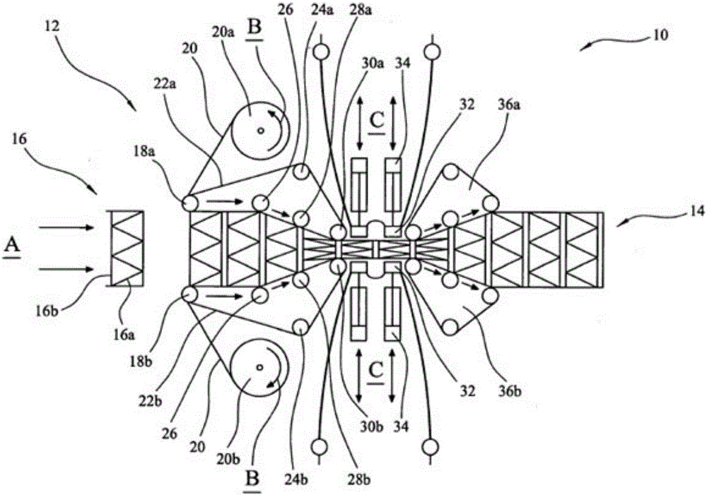
[0034] see figure 1 , which shows an apparatus, generally indicated at 10, for forming a pocket spring unit according to a preferred embodiment of the present invention.

[0035] The device 10 includes an inlet 12 and an outlet 14 . At the entrance, the pocket spring string 16 is shown terminated so that only the last spring is visible. Each spring comprises a coil 16a inside a separate pocket 16b formed of fabric material. The string 16 is fed in the direction of arrow A towards a first set of upper and lower pre-compression rollers, 18a and 18b respectively. At this point, fabric material 20 is introduced above and below the string of springs from fabric rolls 20a and 20b, which rotate in the direction of arrow B. FIG. Material 20 is fed around rollers 18a and 18b on belts 22a and 22b which are synchronously driven by drives 24a and 24b, respectively.

[0036] The uncompressed springs 16 abut each other and pass through the other pair of rollers 26 before reaching the pa...


PUM


Abstract

A method of forming a pocketed spring unit (38) for an upholstered article comprises taking successive strings (16) of pocketed springs and welding at least one sheet of material (20) to at least a first end of the pocketed springs. Anvils (46) are moved from a non- operative position to an operative position, in which they are located between adjacent pockets at upper and lower ends of the springs. This embodiment makes use of the surplus material that is formed at the ends of the pockets in the form of flaps (50) or "ears" of material. These flaps (50) protrude upwardly initially, and then become folded flat as the spring unit advances between the rolls (48) of material. The external anvils (44) are then made to apply heat and pressure to the material flaps (50) trapped between them and the internal anvils (46) at the sides of the pockets, between the springs to weld them to the material from the rolls (48).

Description

technical field [0001] The present invention relates to pocket spring units, and to methods and apparatus for forming such pocket spring units, and in particular to substantially adhesive-free pocket spring units, and methods and apparatus for forming such units. Background technique [0002] Pocket springs, also known as wrap springs, are used in upholstered items such as mattresses. Most pocket spring units consist of a coil spring individually wrapped in a pocket of fabric material by folding over a sheet of fabric to form two leaves enclosing the spring and then attaching the leaves together, between the springs , thus forming a spring string. The strings of springs are then connected together to form a spring array as a pocket spring unit. The springs are joined together to form an array by gluing strings of springs together along the cylindrical surface of the pocket spring, string after string, and so on, until the unit is formed, or by stringing springs together in...

Claims


Application Information

Patent Timeline
IPC IPC(8): A47C27/06B68G9/00B68G15/00
CPCA47C27/064B68G15/00B68G9/00
Inventor 大卫·克莱尔西蒙·保罗·斯平克斯理查德·埃塞里迈克尔·加拉格尔
Owner HARRISON SPINKS COMPONENTS
Why Eureka
Try Eureka