Impedance matching circuit of antenna and terminal

An impedance matching circuit and antenna matching network technology, applied in the field of communications, can solve the problems of difficult debugging, unsatisfactory antenna performance, and difficulty in taking into account all frequency bands at the same time, so as to improve antenna performance, reduce matching difficulty, and achieve simple effects.

Inactive Publication Date: 2016-12-07
SHANGHAI MORUAN COMM TECH
View PDF4 Cites 6 Cited by
  • Summary
  • Abstract
  • Description
  • Claims
  • Application Information

AI Technical Summary

Problems solved by technology

[0003] In the process of realizing the present invention, the inventor found that there are the following problems: the current mobile phone antenna covers more and more frequency bands, due to the large difference in characteristic impedance between the high and low frequency bands of the antenna, and the traditional antenna matching network consists of a fixed value of inductance and The fixed-value capacitor composition, either in the high-frequency band of the antenna makes the antenna and the RF circuit better matched, or in the low-frequency band of the antenna makes the antenna and the RF circuit better matched, it is difficult to take into account all frequency bands at the same time
[0004] Moreover, the traditional antenna matching network needs to eliminate the reactance part of the antenna, and the sum of its own resistance value and the resistance value of the antenna must be close to the resistance value of the radio frequency circuit, which makes debugging difficult and the performance of the antenna is not ideal.

Method used


Image

  • Impedance matching circuit of antenna and terminal
  • Impedance matching circuit of antenna and terminal
  • Impedance matching circuit of antenna and terminal

Examples


Embodiment Construction

[0020] In order to make the object, technical solution and advantages of the present invention clearer, various embodiments of the present invention will be described in detail below in conjunction with the accompanying drawings. However, those of ordinary skill in the art can understand that, in each implementation manner of the present invention, many technical details are provided for readers to better understand the present application. However, even without these technical details and various changes and modifications based on the following implementation modes, the technical solution claimed in this application can also be realized.

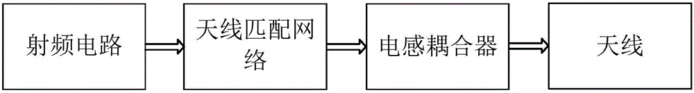
[0021] The first embodiment of the present invention relates to an impedance matching circuit for an antenna, including an antenna matching network and an inductive coupler, and its circuit structure block diagram is as follows figure 1 shown.

[0022] The antenna matching network and the inductive coupler are connected in series between t...


PUM


Abstract

The invention relates to the technical field of communication, and discloses an impedance matching circuit of an antenna and a terminal. In the invention, the impedance matching circuit of the antenna comprises an antenna matching network and an inductive coupler, wherein the antenna matching network and the inductive coupler are serially connected between a radio-frequency circuit and the antenna; the impedance of the antenna is R+jX, R is a resistance value, X is a reactive component, and j is an imaginary part unit; the impedance of the antenna matching network is _jX, the resistance value of the antenna matching network is zero, and the reactive component is equal to X; and the sum of the resistance value of the inductive coupler and the resistance value of the antenna is equal to the resistance value of the radio-frequency circuit. The embodiment of the invention further provides the terminal. Compared with the prior art, the embodiment of the invention can reduce the matching difficulty of the antenna and the radio-frequency circuit, the promotion of antenna performance is facilitated, and the implementation is simple.

Description

technical field [0001] The invention relates to the technical field of communication, in particular to an antenna impedance matching circuit and a terminal. Background technique [0002] In a mobile terminal, an antenna needs to be used to receive and transmit signals, and in the process of receiving signals by the antenna, whether the impedance matching between the antenna and the radio frequency circuit will directly affect the performance of the antenna for transmitting and receiving signals. [0003] In the process of realizing the present invention, the inventor found that there are the following problems: the current mobile phone antenna covers more and more frequency bands, due to the large difference in characteristic impedance between the high and low frequency bands of the antenna, and the traditional antenna matching network consists of a fixed value of inductance and The capacitor composition of a fixed value, either in the high frequency band of the antenna make...

Claims


Application Information

Patent Timeline
Patent Type & Authority Applications(China)
IPC IPC(8): H01Q23/00
CPCH01Q23/00
Inventor 严震辉
Owner SHANGHAI MORUAN COMM TECH
Why Eureka
Try Eureka