
Vent grid and electronic apparatus employing the same

a technology of electronic equipment and vent grid, which is applied in the direction of electrical equipment casings/cabinets/drawers, electrical equipment construction details, instruments, etc., can solve the problems of deteriorating efficiency of cooling fan and cooling performance, leaking electromagnetic waves out of enclosures, and erroneous peripheral performance, so as to increase the cross-sectional area , the effect of increasing the cross-sectional area

Inactive Publication Date: 2007-10-02
FUJITSU LTD
View PDF14 Cites 6 Cited by
  • Summary
  • Abstract
  • Description
  • Claims
  • Application Information

AI Technical Summary

Benefits of technology

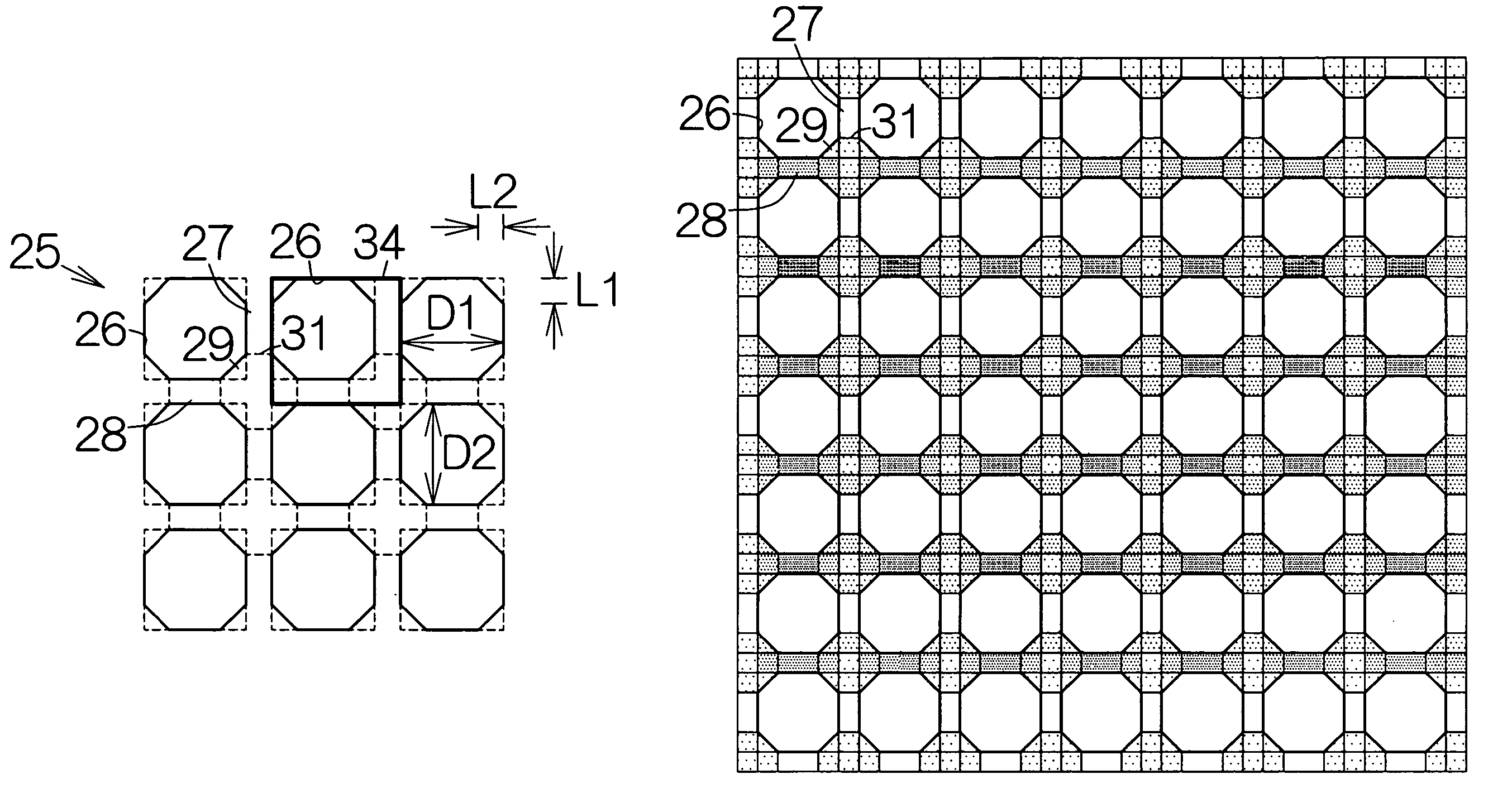
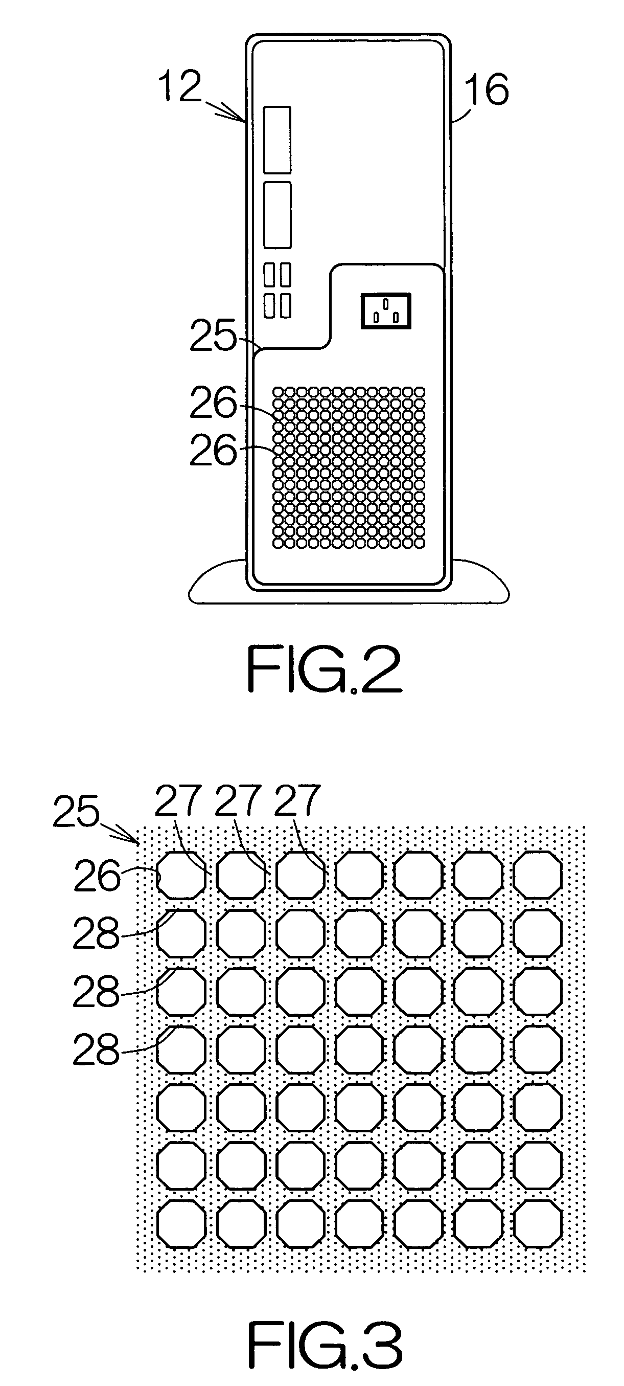
The present invention provides a vent grid and an electronic apparatus that can efficiently avoid inducing electromagnetic wave without compromising cooling efficiency. The vent grid includes parallel first and second electrically-conductive members that have a constant cross-sectional area. An electrically-conductive piece is located at a corner of an opening surrounded by adjacent members, which increases the cross-sectional area of the first and second members and interrupts the flow of electric current. This prevents the vent grid from inducing electromagnetic wave and ensures sufficient airflow for cooling. The electronic apparatus integrates the electrically-conductive piece with the first and second members in the vent grid.

Problems solved by technology

An increased clock frequency of the central processing unit causes leakage of the electromagnetic wave out of the enclosure through the openings of the vent grid.
The leaked electromagnetic wave sometimes causes erroneous performance of the peripherals.
However, a reduced area of the opening leads to a deteriorated efficiency of the cooling fan and cooling performance.

Method used


Image

  • Vent grid and electronic apparatus employing the same
  • Vent grid and electronic apparatus employing the same
  • Vent grid and electronic apparatus employing the same

Examples


Embodiment Construction

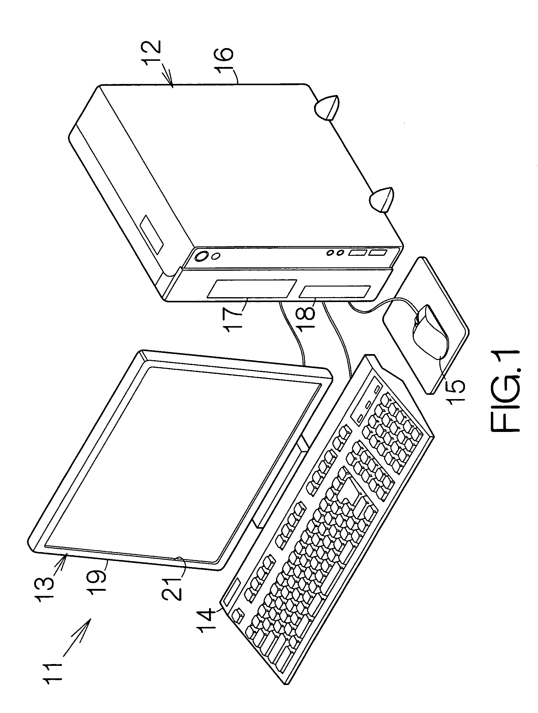
[0024]FIG. 1 schematically illustrates the structure of a desktop computer system as an example of an information processing apparatus. The desktop computer system 11 includes a computer 12 as an example of an electronic apparatus and a display apparatus 13 connected to the computer 12. Input devices such as a keyboard 14, a mouse 15, and the like, are also connected to the computer 12.

[0025]The computer 12 includes a box-shaped enclosure 16. A motherboard is enclosed within the enclosure 16. As conventionally known, electronic circuit elements such as a central processing unit, CPU, a memory, and the like, are mounted on the motherboard. The central processing unit executes various processing and calculation based on software programs and data temporarily stored in the memory, for example. The software programs and data may be stored in a mass storage such as a hard disk drive, HDD, likewise enclosed inside the enclosure 16. The user is allowed to input various data and instruction...


PUM


Abstract

A vent grid has parallel first electrically-conductive members and parallel second electrically-conductive members intersecting with the first electrically-conductive members. The intersection between the first and second electrically-conductive members is forced to have a larger cross-sectional area. The characteristic impedance thus increases. The electric current flowing through the first and second electrically-conductive members turns over at the boundary between the intersection and the first and second electrically-conductive members. The flow of the electric current is in this manner interrupted. Accordingly, the vent grid fails to induce electromagnetic wave. Moreover, the electrically-conductive piece is merely located at a corner of the opening. Decrease in the percentage of the opening is thus suppressed to the utmost per a unit area. A sufficient airflow can be established through the vent grid. Decrease in the cooling efficiency and performance can be suppressed.

Description

BACKGROUND OF THE INVENTION[0001]1. Field of the Invention[0002]The present invention relates to a vent grid utilized in an electronic apparatus, for example.[0003]2. Description of the Prior Art[0004]A computer includes an enclosure. A vent grid is incorporated in the back wall of the enclosure, for example. The vent grid defines a matrix of square openings, for example. A cooling fan is enclosed inside the enclosure. The cooling fan serves to generate airflow circulating through the enclosure. The airflow absorbs heat from a motherboard likewise enclosed inside the enclosure. The heated airflow is discharged out of the enclosure through the openings of the vent grid. The circulation of the airflow in this manner contributes to establishment of a lower temperature inside the enclosure.[0005]An electronic circuit element such as a central processing unit, CPU, is mounted on the motherboard. The central processing unit radiates electromagnetic wave. An increased clock frequency of th...

Claims


Application Information

Patent Timeline
Patent Type & Authority Patents(United States)
IPC IPC(8): H05K9/00
CPCG06F1/18H05K9/0041G06F1/20
Inventor SAKAMOTO, SHIGEONAGASE, KENJITAYA, KAZUAKI
Owner FUJITSU LTD
Learn More