Branch line directional coupler, design method thereof, and electronic equipment

A technology of directional couplers and branch lines, which is applied in the direction of circuits, electrical components, waveguide devices, etc., can solve the problems of machining accuracy limitation, application limitation, and circuit complexity increase, and achieve large working bandwidth, simple design method, and high efficiency. Effect of characteristic impedance

Inactive Publication Date: 2021-09-21
AEROSPACE INFORMATION RES INST CAS
View PDF2 Cites 6 Cited by
  • Summary
  • Abstract
  • Description
  • Claims
  • Application Information

AI Technical Summary

Problems solved by technology

[0006] The multi-level branch line directional coupler using the microstrip line structure is limited by the actual processing accuracy, and cannot achieve the required high characteristic impedance by reducing the width of the transmission line, thus limiting the application in broadband scenarios;
[0007] Introducing additional branch structure or high and low impedance line design to the branch line of the circuit increases the complexity of the circuit, which is not conducive to the requirements of simulation design and circuit miniaturization

Method used


Image

  • Branch line directional coupler, design method thereof, and electronic equipment
  • Branch line directional coupler, design method thereof, and electronic equipment
  • Branch line directional coupler, design method thereof, and electronic equipment

Examples


Embodiment Construction

[0050] The essence of the technical solutions of the embodiments of the present application will be explained in detail below in conjunction with the accompanying drawings.

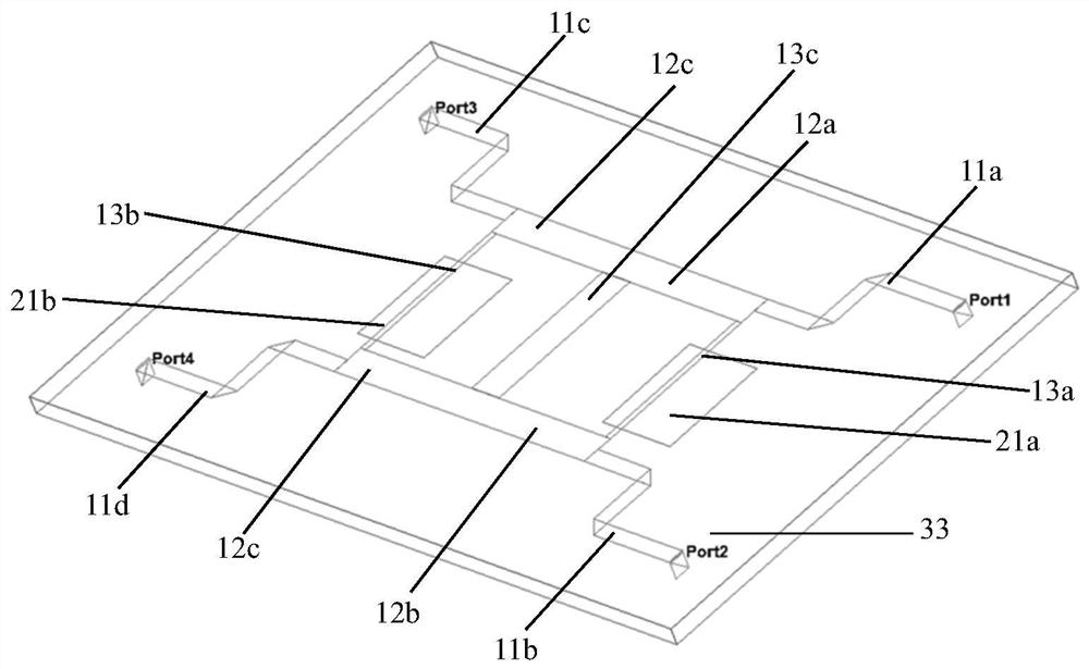
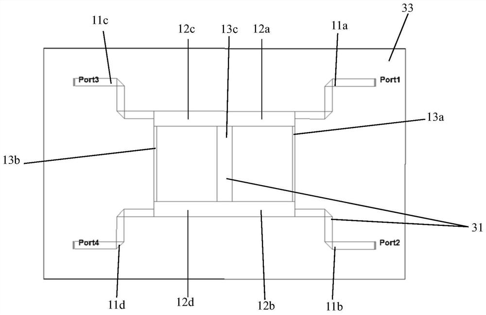
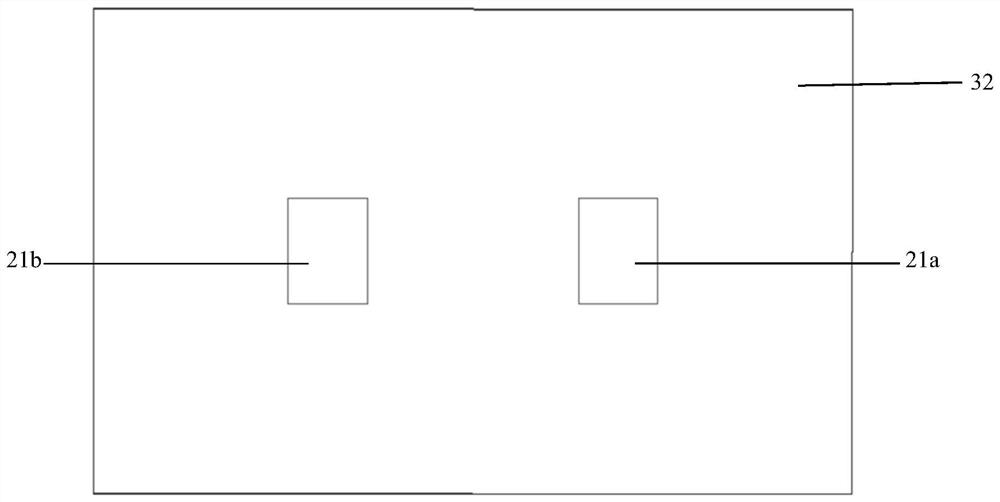
[0051]The embodiment of the present application aims at the high impedance requirement of the branch line of the directional coupler, and utilizes the high impedance characteristics of the defect ground structure to design a load defect ground structure for the high impedance branch line part, and further improve its performance under the premise that a wider transmission line can be realized in actual processing. The characteristic impedance is to meet the design requirements of the principle impedance. At the same time, the physical size of the transmission line can be shortened by utilizing the slow wave effect generated by the structural transmission line loaded with defects, which is beneficial to the miniaturization design of the circuit. The design process of the directional coupler in the embodime...


PUM


Abstract

The invention relates to a branch line directional coupler, a branch line directional coupler design method and electronic equipment. The coupler includes: a first circuit layer having port transmission lines, a coupling line, and a branch line, wherein the port transmission lines being connected to respective ends of the coupling line, the branch line being connected to the coupling line; a second circuit layer provided with a defected ground structure, wherein the defected ground structure corresponds to the branch line in position; and a dielectric layer arranged between the first circuit layer and the second circuit layer. A large working bandwidth is realized, a multi-line layer structure is adopted, the design method is simple, and miniaturization and integration design of the circuit is easy to realize.

Description

technical field [0001] The embodiments of the present application relate to a directional coupler, and in particular to a branch line directional coupler, a design method for a branch line directional coupler, and an electronic device. Background technique [0002] As an important basic structure of microwave radio frequency circuit, the directional coupler is used to distribute the power of the input microwave signal according to a certain ratio. It is widely used in signal isolation, separation and mixing, such as power monitoring, source output power stabilization, etc. Amplitude, signal source isolation, frequency sweep test of transmission and reflection, etc. [0003] Directional couplers are generally composed of transmission lines, and coaxial lines, waveguides, striplines and microstrip lines can form directional couplers. Among them, the branch line structure directional coupler is a directional coupler with two parallel transmission lines and multiple branch line...

Claims


Application Information

Patent Timeline
Patent Type & Authority Applications(China)
IPC IPC(8): H01P5/18
CPCH01P5/184
Inventor 李霁晨刘开雨李天龙王宇
Owner AEROSPACE INFORMATION RES INST CAS
Why Eureka
Try Eureka