Automatic polishing separator

A separator and finishing technology, applied in magnetic separation, solid separation, chemical instruments and methods, etc., can solve problems such as troublesome operation procedures of oil switch finishing devices, achieve simple results, reduce labor intensity, and improve work efficiency Effect

Active Publication Date: 2017-08-25
EAST SEALING TECH (JIANGSU) CO LTD
View PDF7 Cites 1 Cited by
  • Summary
  • Abstract
  • Description
  • Claims
  • Application Information

AI Technical Summary

Problems solved by technology

[0004] The present invention intends to provide an automatic finishing separator to solve the troublesome operation procedure of the traditional oil switch finishing device

Method used


Image

  • Automatic polishing separator
  • Automatic polishing separator

Examples


Embodiment Construction

[0014] The present invention will be described in further detail below by means of specific embodiments:

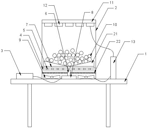
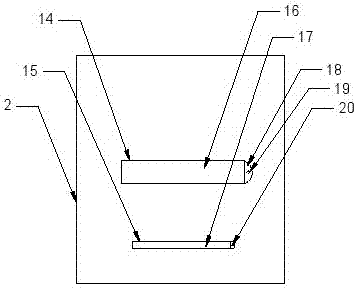
[0015] The reference signs in the drawings of the description include: base 1, processing box 2, power switch 3, partition plate 4, ventilation hole 5, rotating shaft 6, stirring rod 7, motor 8, fan 9, steel ball 10, top plate 11 , electromagnet 12, control switch 13, first side hole 14, second side hole 15, first sealing plate 16, second sealing plate 17, lug 18, limiting hole 19, limiting protrusion 20, fixing plate 21. Filter screen 22.

[0016] The embodiment is basically as attached figure 1 , figure 2 Shown: automatic finishing separation machine, including base 1, processing box 2 and power switch 3, processing box 2 is located in the middle of base 1, power switch 3 is set on the left side of base 1, and processing box 2 is fixed A partition plate 4 is provided, and a plurality of ventilation holes 5 are provided on the partition plate 4 .

[0017] The middle...


PUM


Abstract

The invention discloses an automatic polishing-separating machine which comprises a base, a machining box and a power switch, wherein the machining box is positioned at the middle of the base; the power switch is arranged on one side of the base; a separating plate is arranged in the machining box; a plurality of vent holes are formed in the separating plate; a rotating shaft is arranged at the middle of the separating plate, and rotationally connected with the bottoms of the separating plate and the machining box; a plurality of stirring rods are circumferentially arranged at one end of the rotating shaft in the machining box; a motor is arranged at the other end of the rotating shaft; a plurality of draught fans are arranged between the bottoms of the separating plate and the machining box; a plurality of hollow steel balls are arranged on the separating plate; the ball diameter of each steel ball is greater than the hole diameter of each vent hole; a top plate is hinged with the top of the machining box; a plurality of electromagnets used for adsorbing the steel balls are arranged on the top plate, and connected with a control switch; the draught fans and the control switch are electrically connected with each other; and the motor and the power switch are electrically connected with each other. By adoption of the automatic polishing-separating machine disclosed by the invention, the problem that a conventional oil switch polishing device is complex in operation procedure can be mainly solved.

Description

technical field [0001] The invention belongs to the field of special machine tools or devices, and in particular relates to an automatic light decoration separating machine. Background technique [0002] Equipped with transformer oil, the contacts of the switch are immersed in the oil to prevent oxidation, and the contacts are dissipated, and the switch that ensures reliable insulation between the high-voltage contacts and the ground is called an oil switch. [0003] There are many places where the oil switch is used, and its importance is also extremely high. The oil switch will go through multiple processes from processing to delivery, among which the finishing of the oil switch is particularly important, because the degree of finishing of the oil switch directly affects the later use. At present, the finishing device for the oil switch is mainly to add the oil switch and steel balls in the chamber, and use the steel balls to polish the oil switch. After finishing the fin...

Claims


Application Information

Patent Timeline
Patent Type & Authority Patents(China)
IPC IPC(8): B03C1/02
CPCB03C1/02
Inventor 涂国荣徐飞林锋周玉明涂鑫豪
Owner EAST SEALING TECH (JIANGSU) CO LTD
Why Eureka
Try Eureka