Plane inflexion type elastic intensified heat exchange tube bundle and heat exchanger
A technology of heat exchange tube bundle and heat exchange tube, applied in the direction of heat exchanger type, heat exchanger shell, indirect heat exchanger, etc., can solve the problem of not reaching the ideal state of fluid-induced vibration to enhance heat transfer
- Summary
- Abstract
- Description
- Claims
- Application Information
AI Technical Summary
Problems solved by technology
Method used
Image

Examples
Embodiment 1
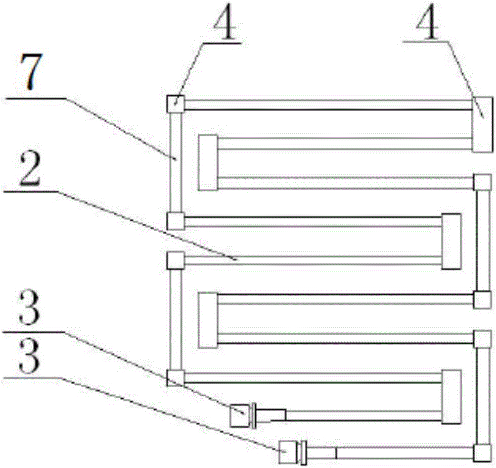
[0039] Example 1: A planar folded type elastically reinforced heat exchange tube bundle, the structure of which is as follows figure 1 shown, including:
[0040] A plurality of first heat exchange tubes 2;
[0041] The direction of the first heat exchange tube 2 is different and the second heat exchange tube 7 is in the same plane; both ends of each second heat exchange tube 7 are airtightly connected with the slider 4, and each slider 4 is at least It is airtightly connected with one first heat exchange tube 2 .
[0042] Wherein, the axes of any first heat exchange tube 2 and any second heat exchange tube 7 are perpendicular. And the first heat exchange tube 2 and the second heat exchange tube 7 are both straight tubes.
[0043] Meanwhile, there are at least two first heat exchange tubes 2 .
[0044] In all the first heat exchange tubes 2 , the ends not connected to the sliders 4 have mounting heads 3 .
[0045] The floating block 4 can have two structures, one is hollow...
Embodiment 2
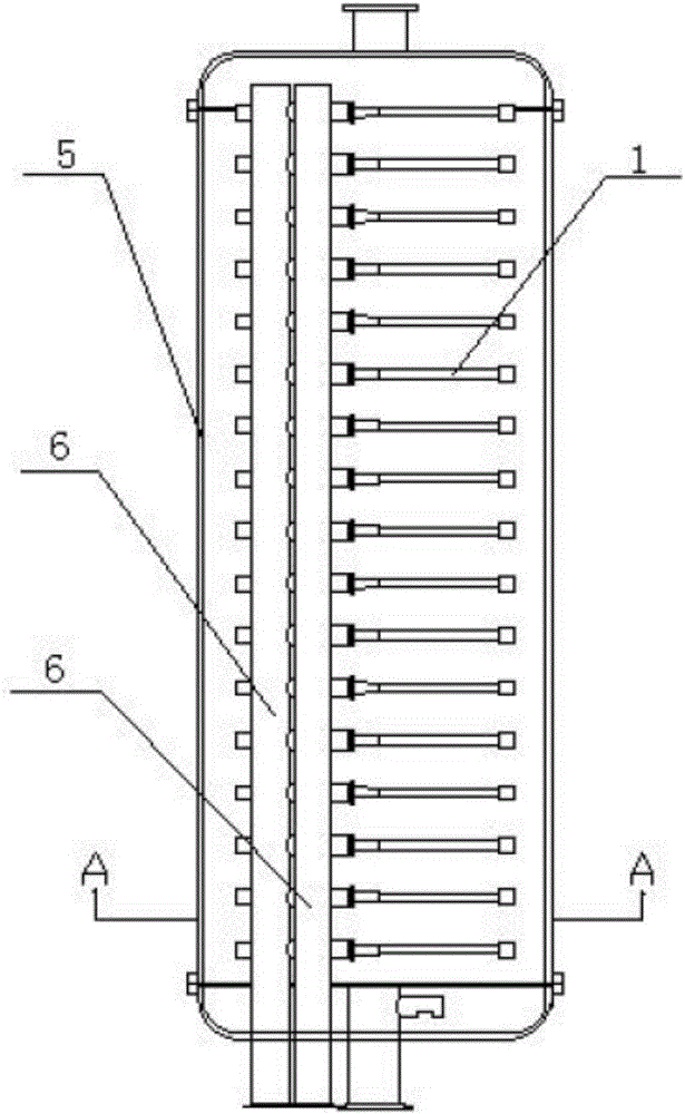
[0049] Embodiment 2: a kind of heat exchanger, its structure is as figure 1 , image 3 and Figure 4 As shown, it has a shell 5, and the shell 5 has a fixed support 6 and a heat exchange tube bundle. The heat exchange tube bundle is the heat exchange tube bundle structure provided in Example 1, and the heat exchange tube bundle is arranged horizontally.
[0050] The principle of this embodiment is: the tube-side fluid enters from one installation head 3 , flows out from the other installation head 3 after passing through the first heat exchange tube 2 , the slider 4 and the second heat exchange tube 7 . The shell-side fluid flows in from the lower end of the heat exchanger shell 5 and flows out from the upper end. When the shell-side fluid flows around the horizontally arranged planar folded elastic tube bundle, the alternating lateral fluid force acting on the elastic tube bundle can cause the heat exchange tube bundle 1 to generate lateral vibration, thereby achieving the...
Embodiment 3
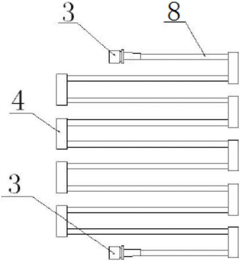
[0056] Embodiment 3: A kind of planar folding type elastic reinforced heat exchange tube bundle, its structure is as follows figure 2 shown, including:
[0057] Multiple heat exchange tubes 8;
[0058] The end of each heat exchange tube 8 is airtightly connected with a floating block 4 , and the end of the heat exchange tube 8 not connected with the floating block 4 has a mounting head 3 .
[0059] All the heat exchange tubes 8 are straight tubes, and there are at least two heat exchange tubes 8 . The axes of all the heat exchange tubes 8 are located in the same plane, so that the heat exchange tubes 8 and the sliders 4 form a heat exchange tube bundle 1 .
[0060] In this embodiment: the floating block 4 is hollow inside, and the two openings are located on the same surface.
[0061] Adopting the above-mentioned structure can make the heat exchange tube form a single-fold structure.
[0062] The heat exchange tube bundle in this embodiment is basically in a horizontal stat...
PUM
 Abstract
Description
Claims
Application Information
 - R&D Engineer
- R&D Manager
- IP Professional
- Industry Leading Data Capabilities
- Powerful AI technology
- Patent DNA Extraction
Browse by: Latest US Patents, China's latest patents, Technical Efficacy Thesaurus, Application Domain, Technology Topic.
© 2024 PatSnap. All rights reserved.Legal|Privacy policy|Modern Slavery Act Transparency Statement|Sitemap