An X-ray image sensor and its method for eliminating image afterimage
An image sensor and X-ray technology, which is used in radiological diagnosis instruments, radiation detection devices, medical science, etc.
- Summary
- Abstract
- Description
- Claims
- Application Information
AI Technical Summary
Problems solved by technology
Method used
Image
Examples
Embodiment 1
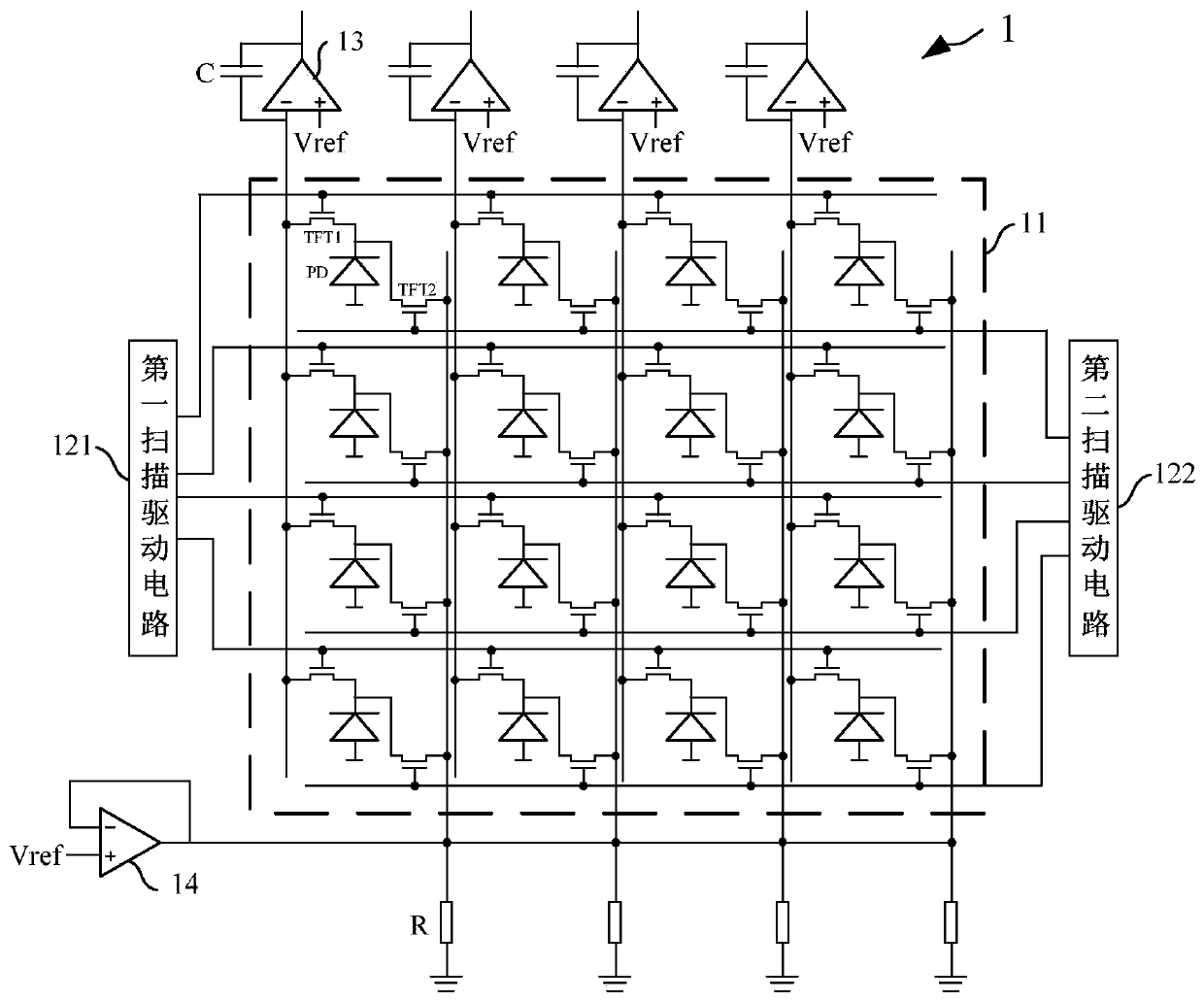
[0055] Such as image 3 As shown, the present invention provides an X-ray image sensor 1, and the X-ray image sensor 1 includes at least:
[0056] The pixel array 11 , the first scan driving circuit 121 , the second scan driving circuit 122 , the readout circuit and the release circuit.
[0057] Such as image 3 As shown, the pixel array 11 includes a plurality of pixel units, and in this embodiment, the pixel array 11 is a 4×4 array. Each pixel unit includes a first TFT switch TFT1 , a second TFT switch TFT2 and a photodiode PD. The first electrode of the first TFT switch TFT1 is connected to the readout circuit, the second electrode is connected to the cathode of the photodiode PD, and the third electrode is connected to the first scanning drive circuit 121; the second TFT switch TFT2 The first electrode of the photodiode is connected to the release circuit, the second electrode is connected to the cathode of the photodiode PD, and the third electrode is connected to the ...
Embodiment 2
[0071] Such as Figure 3 ~ Figure 4 As shown, the present invention also provides a method for eliminating image persistence, the method for eliminating image persistence at least includes:
[0072] Step S1 : before exposure, the second scan driving circuit 122 outputs a driving sequence to clear the residual charge in the pixel unit.
[0073] Specifically, in this embodiment, the X-ray image sensor 1 is used as the hardware basis. Such as image 3 As shown, before exposure, the second scan driving circuit 122 outputs a driving sequence to turn on the second TFT switch TFT2 in each pixel unit row by row, so as to clear the residual charge and leakage information in each pixel unit.
[0074] Step S2: stop the output driving sequence, and perform the exposure operation.
[0075] Specifically, such as image 3 As shown, the first scanning driving circuit 121 and the first scanning driving circuit 122 stop output driving timing, and each first TFT switch TFT1 and each second T...
Embodiment 3
[0084] Such as image 3 and Figure 5 As shown, the present embodiment provides a method for eliminating image sticking, and both the present embodiment and the second embodiment use the X-ray image sensor 1 as the hardware basis. The difference is that, in this embodiment, the bright-field images in the pixel units of each row are sequentially read out row by row, and at the same time, the dark-field residual charges are released for the pixel units that have collected the bright-field images.
[0085] Specifically, the method for eliminating image sticking includes at least:
[0086] Step S1': Before exposure, the second scan driving circuit 122 outputs a driving sequence to clear the residual charge in the pixel unit.
[0087] Specifically, such as image 3 As shown, before exposure, the second scan driving circuit 122 outputs a driving sequence to turn on the second TFT switch TFT2 in each pixel unit row by row, so as to clear the residual charge and leakage information...
PUM
 Abstract
Description
Claims
Application Information
 - R&D
- Intellectual Property
- Life Sciences
- Materials
- Tech Scout
- Unparalleled Data Quality
- Higher Quality Content
- 60% Fewer Hallucinations
Browse by: Latest US Patents, China's latest patents, Technical Efficacy Thesaurus, Application Domain, Technology Topic, Popular Technical Reports.
© 2025 PatSnap. All rights reserved.Legal|Privacy policy|Modern Slavery Act Transparency Statement|Sitemap|About US| Contact US: help@patsnap.com


