
Vacuum booster detector at the push rod position

A vacuum booster and detection device technology, applied in the direction of measuring devices, mechanical measuring devices, mechanical devices, etc., can solve the problems of reduced sealing performance and easy wear and tear

Active Publication Date: 2017-01-25
ACCU JIANGSU CO LTD
View PDF7 Cites 5 Cited by
  • Summary
  • Abstract
  • Description
  • Claims
  • Application Information

AI Technical Summary

Problems solved by technology

[0004] The technical problem solved by the present invention: the vacuum booster push rod detection device in the prior art, the sealing ring provided on the outer wall of the pressure head is easy to be worn during use, and its sealing performance will decline after repeated use

Method used


Image

  • Vacuum booster detector at the push rod position
  • Vacuum booster detector at the push rod position
  • Vacuum booster detector at the push rod position

Examples


Embodiment Construction

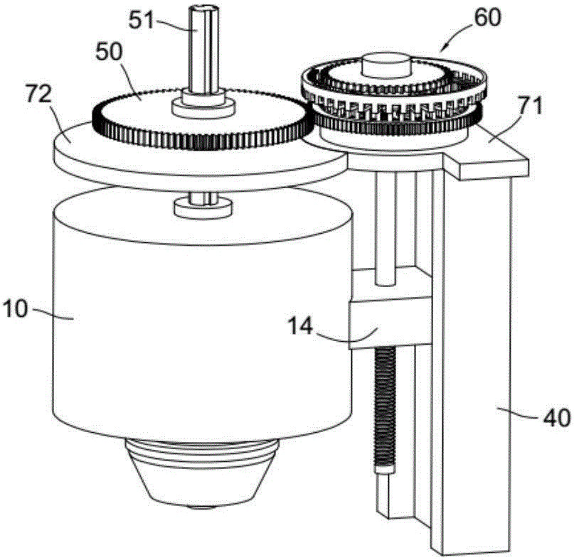
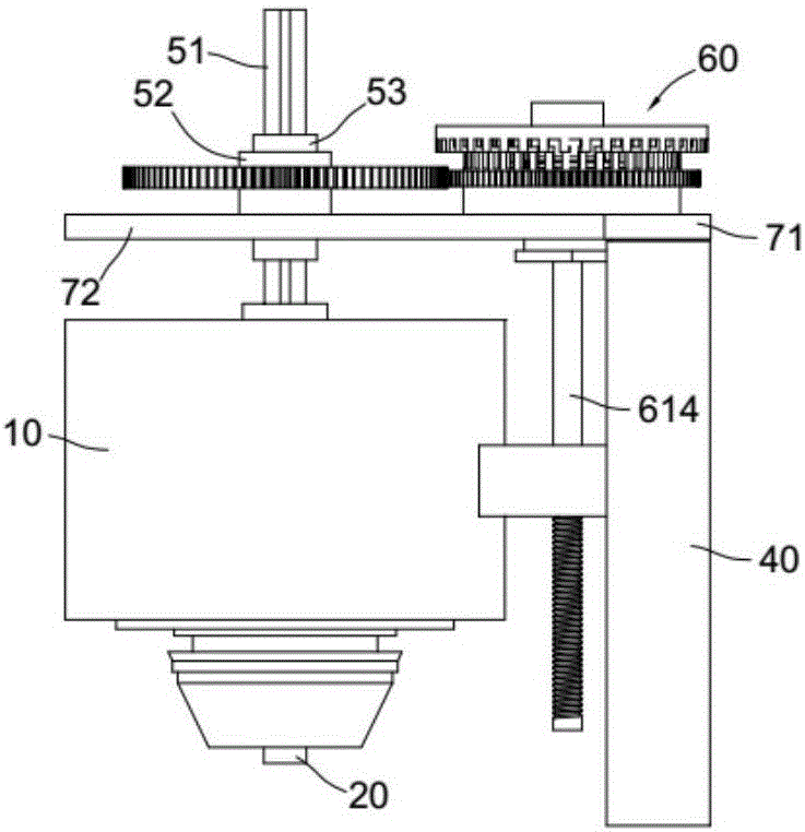
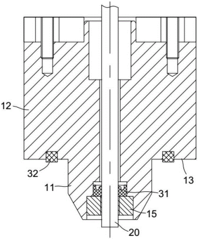
[0046] The following specific implementation refers to Figure 1 to Figure 8 .

[0047] A device for detecting the position of a push rod of a vacuum booster includes an indenter 10, the indenter includes an indenter convex portion 11 inserted into the vacuum booster, and an indenter shoulder 13 is provided between the indenter convex portion and the indenter body 12; An ejector rod 20 is inserted into the indenter, the ejector rod penetrates the indenter, and a first sealing ring 31 is provided between the contact surface of the ejector and the indenter; a second sealing ring 32 is provided on the shoulder of the indenter; The indenter is slidably fitted on the linear slide rail 40, and the linear slide rail is provided with a driving mechanism 60 that drives the indenter to move along the linear slide rail for a fixed displacement.

[0048] The driving mechanism 60 includes a rotating assembly 61, a locking assembly 62 and a driving assembly 63.

[0049] In the driving mechanism ...


PUM


Abstract

A vacuum booster detector at the push rod position has a pressure head which includes a pressure head convex to be inserted into the vacuum booster and connected with the the main body of the pressure head by a pressure head shoulder; there is a mandril within the pressure head and a first seal right is set at the contact surface between the mandril and the pressure head; a second seal ring is set at the pressure head shoulder; the pressure head flows on a linear sliding rail, on which there is no driving mechanism to drive the pressure head. in product detection, the convex of the pressure head enters into the front shell of the product firstly and the pressure head shoulder push against the outer wall of the front shell; under the driving of the driving mechanism, elastic deformation happens on the second seal ring and the pressure head is sealed with the front shell; then, the mandril moves and pushes the push rod and the reaction plate to reset and the push rod height can be measured by measuring the displacement of the mandril.

Description

Technical field [0001] The invention relates to the detection of automobile devices, in particular to the detection of automobile vacuum boosters. Background technique [0002] A push rod is provided in the vacuum booster to push the master cylinder to make the brake master cylinder produce a certain amount of hydraulic pressure. However, during the assembly process of the vacuum booster, the position of the push rod will also vary due to errors, which will affect the push The accuracy of the cylinder, therefore, after the production of the vacuum booster product is completed, the position of the push rod head needs to be detected to ensure the accurate displacement of the push rod head, so as to ensure the safety of the vacuum booster. [0003] In order to solve the above technical problems, the utility model with the authorized announcement number CN 204286295U discloses a vacuum booster push rod detection device, which includes a movable indenter inserted into the vacuum booster...

Claims


Application Information

Patent Timeline
Patent Type & Authority Applications(China)
IPC IPC(8): G01B5/02
CPCG01B5/02
Inventor 尤丹雷
Owner ACCU JIANGSU CO LTD
Learn More