Tool Setting Method for Machining Large Aperture Aspherical Optical Components by Atmospheric Plasma

An optical element and plasma technology, which is applied in the field of tool setting for plasma processing large-diameter aspherical optical elements, can solve the problems of large human influence, difficult to guarantee the precision and quality of the tool, and long operation time, so as to reduce the experience, The effect of improving the precision of tool setting, the quality of assembly and adjustment, the improvement of processing quality and the stability of the process

Active Publication Date: 2018-12-21
成都精密光学工程研究中心
View PDF6 Cites 0 Cited by
  • Summary
  • Abstract
  • Description
  • Claims
  • Application Information

AI Technical Summary

Problems solved by technology

This method relies heavily on the experience and proficiency of the operator, and is greatly influenced by humans, and there are problems such as difficulty in ensuring the accuracy and quality of tool setting, and long operation time.

Method used


Image

  • Tool Setting Method for Machining Large Aperture Aspherical Optical Components by Atmospheric Plasma
  • Tool Setting Method for Machining Large Aperture Aspherical Optical Components by Atmospheric Plasma
  • Tool Setting Method for Machining Large Aperture Aspherical Optical Components by Atmospheric Plasma

Examples


Embodiment Construction

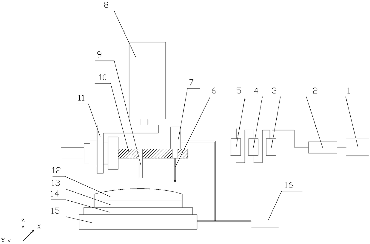
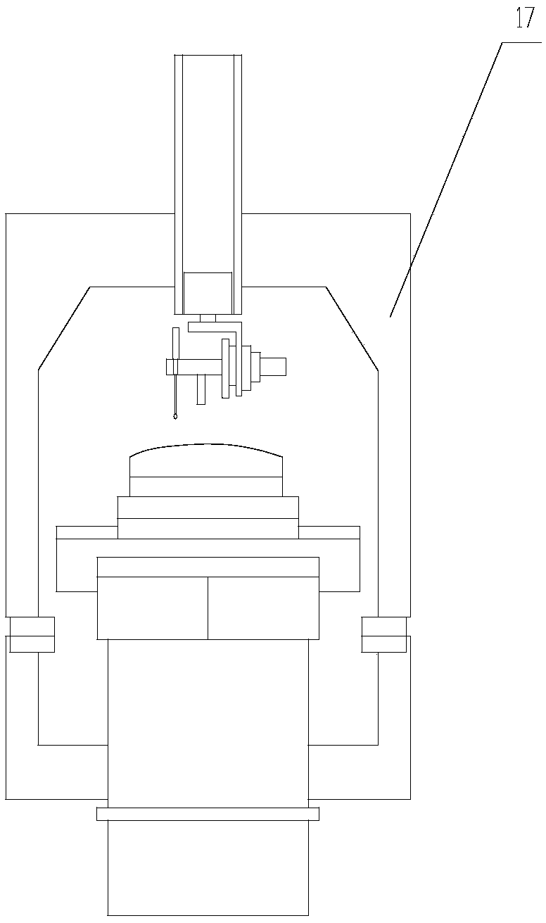
[0023] Such as Figure 1-2 As shown, the present invention consists of an air compressor 1, an air storage tank 2, a filter 3, a solenoid valve 4, a speed control valve 5, a trigger probe 6, a pneumatic sliding table 7, a support frame 10, an adapter plate 11, and a Z-axis Guide rail 8, fixture 13 and two-dimensional adjustment platform 14 constitute. The air compressor 1, the air storage tank 2, the filter 3, the solenoid valve 4, the speed control valve 5 and the pneumatic sliding table 7 are connected through the air pipe in sequence, and the air storage tank 2 stores the energy of the gas generated by the air compressor 1 and The air pressure is stable, the filter 3 filters out the micro-particle impurities in the gas pipeline, the pneumatic sliding table 7 is installed on the support frame 10, the end of the pneumatic sliding table 7 is connected to the three-way high-precision trigger probe 6, and the trigger probe 6 moves up and down. The movement is driven by the pneu...


PUM


Abstract

The invention provides a high-precision cutting tool alignment method for machining a large-caliber non-spherical-surface optical element by atmospheric plasma. The cutting tool alignment method for machining the large-caliber non-spherical-surface optical element by the atmospheric plasma comprises the following steps: firstly, adjusting a side edge of the optical element to be parallel to a horizontal coordinate axis; then leveling the surface of the optical element along the Z direction of a symmetric coordinate position of a central axis; finally, determining a central coordinate of the optical element and positions of a plasma torch center and an optical element center through two-edge cutting tool alignment, so as to finish cutting tool alignment. By comprehensively considering factors in two aspects of cutting tool alignment efficiency and cutting tool alignment precision, a traditional fixed type thimble head is replaced with a high-precision triggering measuring head. By adopting the cutting tool alignment method provided by the invention, influences caused by manual factors including experience of operators, an observation angle and the like are reduced; the cutting tool alignment precision and assembling and adjustment quality of the optical element are extremely improved; the operation convenience and the cutting tool alignment efficiency are improved, and the machining quality and the technological stability are easy to improve.

Description

technical field [0001] The invention belongs to the field of optical processing, and in particular relates to a tool setting method for processing large-diameter aspheric optical elements by atmospheric plasma. Background technique [0002] Atmospheric plasma processing technology is an innovative technology developed in the field of optical processing in recent years, especially for the processing of optical components of hard and brittle materials (such as: fused silica, silicon carbide, etc.) and has extremely important value. The processing principle is: use the chemical reaction between the high-density and highly reactive atoms generated by the plasma excitation under normal pressure and the surface atoms of the material to generate volatile reaction products, so as to realize the efficient removal of materials. Plasma processing is a non-contact chemical processing that does not introduce subsurface damage, and has unique advantages in optical element processing. [...

Claims


Application Information

Patent Timeline
Patent Type & Authority Patents(China)
IPC IPC(8): C03C15/00
CPCC03C15/00
Inventor 金会良张清华邓文辉唐才学徐曦袁志刚侯晶陈贤华
Owner 成都精密光学工程研究中心
Why Eureka
Try Eureka