Rolling rotor compressor with servo ring hinged blades

A technology of rolling rotor and follower ring, applied in the field of compressors, can solve the problems of difficult to reduce production cost, easy damage of parts and high energy consumption in operation

Inactive Publication Date: 2002-07-03
付云树
View PDF1 Cites 0 Cited by
  • Summary
  • Abstract
  • Description
  • Claims
  • Application Information

AI Technical Summary

Problems solved by technology

High energy consumption in operation, easy damage to components lead to short service life of the whole machine, and difficulty in reducing production costs. These are the problems that must be solved for rolling rotor compressors seen today.

Method used


Image

  • Rolling rotor compressor with servo ring hinged blades
  • Rolling rotor compressor with servo ring hinged blades
  • Rolling rotor compressor with servo ring hinged blades

Examples


Embodiment Construction

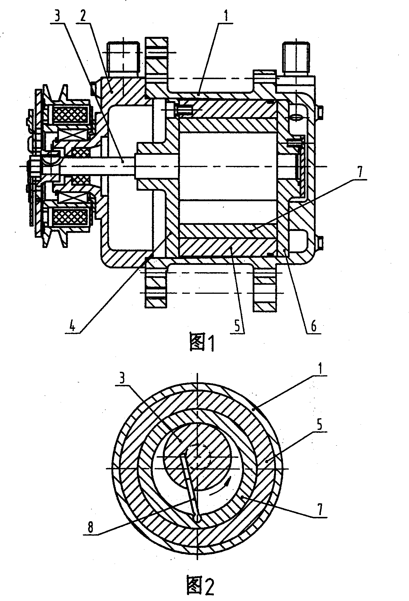
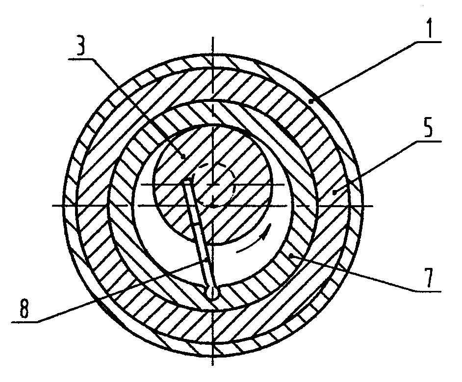
[0011] In the specific implementation process, the casing of the compressor of the present invention is best divided into two parts, the casing 1 and the casing cover 2, as shown in Figure 1. After the cylinder assembly can be fitted in the cavity of the casing 1, Then buckle the shell cover 2 to form the whole machine. The shell 1 and the cover 2 can be made of lightweight materials such as aluminum alloy. The drive shaft 3 is a concentric shaft with all shaft steps. The projecting holes of the drive shaft 3 on the shell cover 2 and the bearing housing holes on the front cylinder head 4 and the rear cylinder head 6 can be connected between the drive shaft 3 and the cylinder barrel. 5 After the eccentric distance of the axis line of the inner cavity (actually from the inner circular cavity of the follower ring 7) is determined, one positioning and boring is performed. Because the cylinder tube 5 of the compressor of the present invention does not need to be provided with a longitu...


PUM


Abstract

The new type compressor is constituted by a cylinder assembly, which consists of driving shaft, cylinder, front and back caps, servo ring and isolating blade, installed in the casing cavity. It features the concentric driving shaft steps, the servo ring inside the cylinder, the eccentric driving shaft and the silating blade with outer end hinged with the servo ring and inner end inserted inside the straight runner. During the rotation of the driving shaft, the isolating blade rotates the servo ring to suck in and extrude out cold medium. The compressor has no eccentric vibration, and thus good high speed performance.

Description

1. Technical Field: [0001] The invention relates to a compressor used in refrigeration devices of automobiles, refrigerators, freezers and household air conditioners, in particular to a follower ring hinged blade rolling rotor compressor. 2. Background technology: [0002] The currently seen rolling rotor compressors use straight isolation blades in the cylinder chamber to press an eccentric rolling ring to compress the refrigerant. The straight isolating blade is fitted in a straight groove longitudinally opened on a longitudinal straight long wall specially arranged on the outer wall of the cylinder tube of the cylinder. A spring is installed in the straight long groove of the cylinder wall to press the top plane of the straight isolation blade, so that the straight isolation blade tightly abuts the rolling ring. The protruding straight long wall on the outer wall of the cylinder tube greatly increases the difficulty of the processing technology of the cylinder tube. This struc...

Claims


Application Information

Patent Timeline
Patent Type & Authority Patents(China)
IPC IPC(8): F04C18/32
Inventor 付云树
Owner 付云树
Why Eureka
Try Eureka