
an underwater vehicle

An underwater vehicle, single-frame technology, used in underwater ships, underwater operation equipment, special-purpose ships, etc., can solve the problems of destroying the flow field, corrosion, destroying the integrity of the vehicle shell, etc., and achieve vibration suppression. Noise, effect of zero radius of gyration

Active Publication Date: 2017-10-13
HUAZHONG UNIV OF SCI & TECH
View PDF5 Cites 1 Cited by
  • Summary
  • Abstract
  • Description
  • Claims
  • Application Information

AI Technical Summary

Problems solved by technology

Therefore, for a vehicle with a certain speed, if only the rudder is used as the actuator for attitude control, the vehicle needs a larger radius of gyration, which is not conducive to the operation of the vehicle in a small space.
[0004] 2) The control force (moment) generated by the rudder and paddle is generated by the interaction with the fluid, so it is easily affected by the flow field, and it is difficult to achieve precise attitude control, especially when working in a complex flow field environment
First of all, the existence of the paddle destroys the integrity of the aircraft shell to a certain extent, which is not conducive to the rapidity, pressure resistance and manufacturability of the aircraft; secondly, the paddle is exposed in seawater and is seriously polluted by marine organisms and seawater corrosion ; In addition, a single propeller can only provide a moment in one direction. If the aircraft is to be able to maneuver at any attitude angle, at least a plurality of propellers are required (except for the propellers used to provide thrust); moreover, the mutual contact between the propeller and the water is still Noise will be generated, which is very unfavorable for aircraft with stealth performance requirements (such as torpedoes); finally, the mutual contact between paddles and water will destroy the characteristics of the flow field. When the field is affected, it is not conducive to the operation of underwater vehicles
In addition, for some small or miniature underwater vehicles, the limited space is not conducive to the arrangement of attitude control paddles

Method used


Image

  • an underwater vehicle
  • an underwater vehicle
  • an underwater vehicle

Examples


Embodiment Construction

[0026] In order to make the object, technical solution and advantages of the present invention clearer, the present invention will be further described in detail below in conjunction with the accompanying drawings and embodiments. It should be understood that the specific embodiments described here are only used to explain the present invention, not to limit the present invention. In addition, the technical features involved in the various embodiments of the present invention described below can be combined with each other as long as they do not constitute a conflict with each other.

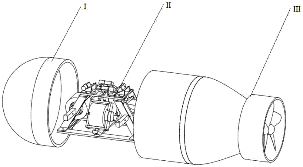
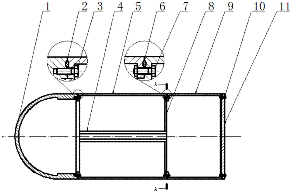
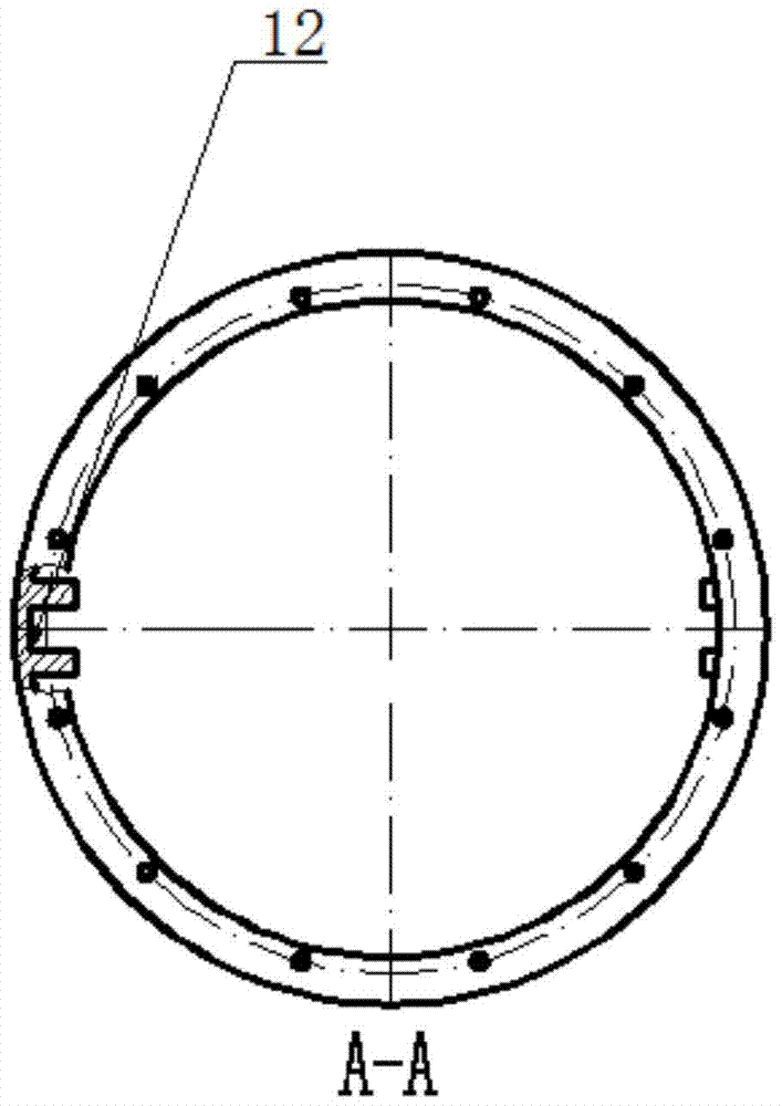
[0027] refer to Figure 1 to Figure 7 , an underwater vehicle, comprising a casing I and an impeller assembly III mounted on the casing I, a gyro assembly II is installed in the casing I, and the gyro assembly II includes a gyro bracket 16 and is installed on the gyro bracket The control moment gyro group on 16, where,

[0028] The control moment gyroscope group includes four single-frame cont...


PUM


Abstract

The invention discloses an underwater vehicle, which comprises a casing and an impeller assembly installed on the casing. A gyro assembly is installed in the casing. The gyro assembly includes a gyro bracket and a control moment gyro group. The control moment gyro group includes four single The frame control moment gyroscope, each single frame control moment gyroscope includes a single frame, a gyro rotor, a single frame shaft, a single frame drive motor and a gyro rotor drive motor, the single frame drive motor is installed on the gyro bracket and drives the single frame through the single frame shaft The frame rotates, the gyro rotor driving motor and the gyro rotor are installed on the single frame, and the gyro rotor is driven to rotate by the gyro rotor driving motor. The control moment gyro group of the present invention can provide continuous and smooth output torque, which meets the requirements for agility and precision in navigation, and can realize zero turning radius under the state of zero momentum, greatly improving the maneuverability of the aircraft .

Description

technical field [0001] The invention belongs to the field of underwater vehicles, and more specifically relates to an underwater vehicle. Background technique [0002] At present, the attitude control actuators of most underwater vehicles are rudders and oars. Generally, the aircraft uses the rudder to control its attitude when it is moving at high speed, and uses the paddles to adjust its attitude when it is at low speed or zero speed. It has the following characteristics: [0003] 1) When the aircraft is at low speed or zero speed, the rudder effect is lost. Therefore, for a vehicle with a certain speed, if only the rudder is used as the actuator for attitude control, the vehicle needs a larger radius of gyration, which is not conducive to the operation of the vehicle in a small space. [0004] 2) The control force (moment) generated by the rudder and paddle is generated by the interaction with the fluid, so it is easily affected by the flow field, and it is difficult t...

Claims


Application Information

Patent Timeline
Patent Type & Authority Patents(China)
IPC IPC(8): B63G8/14
Inventor 唐国元黄道敏刘泽宇张超华朱秋晨邱威杨东超陈龙
Owner HUAZHONG UNIV OF SCI & TECH
Learn More