
A swash plate hydraulic axial piston pump/motor heavy-duty slipper pair anti-friction disc

An axial piston pump and swash plate type technology, which is applied in the field of swash plate hydraulic axial piston pump/motor heavy-duty slipper pair anti-friction disc, which can solve the problem of being sensitive to influence and difficult to satisfy slipper pair friction lubrication. Bearing performance design requirements and other issues to achieve the effect of reducing frictional power loss, easy maintenance and replacement, and sufficient lubrication and cooling

Active Publication Date: 2020-02-18
HEFEI UNIV OF TECH
View PDF6 Cites 0 Cited by
  • Summary
  • Abstract
  • Description
  • Claims
  • Application Information

AI Technical Summary

Problems solved by technology

[0005] The research on the anti-friction technology and methods of sliding shoe pair at home and abroad shows that due to the static pressure support characteristics of the sliding shoe pair, the anti-friction and anti-wear function of the surface morphology of the friction interface of the sliding shoe pair will be inhibited to a certain extent. There is no ideal method for the tribological design of shoe pairs and improving the friction and lubrication performance of sliding shoe pairs. Sensitive, it is difficult to meet the design requirements of the friction and lubrication load-carrying performance of the sliding shoe pair under a wide range of working conditions. The anti-friction and anti-wear technology and methods of boot pairs still need more and more in-depth research

Method used


Image

  • A swash plate hydraulic axial piston pump/motor heavy-duty slipper pair anti-friction disc
  • A swash plate hydraulic axial piston pump/motor heavy-duty slipper pair anti-friction disc
  • A swash plate hydraulic axial piston pump/motor heavy-duty slipper pair anti-friction disc

Examples


Embodiment Construction

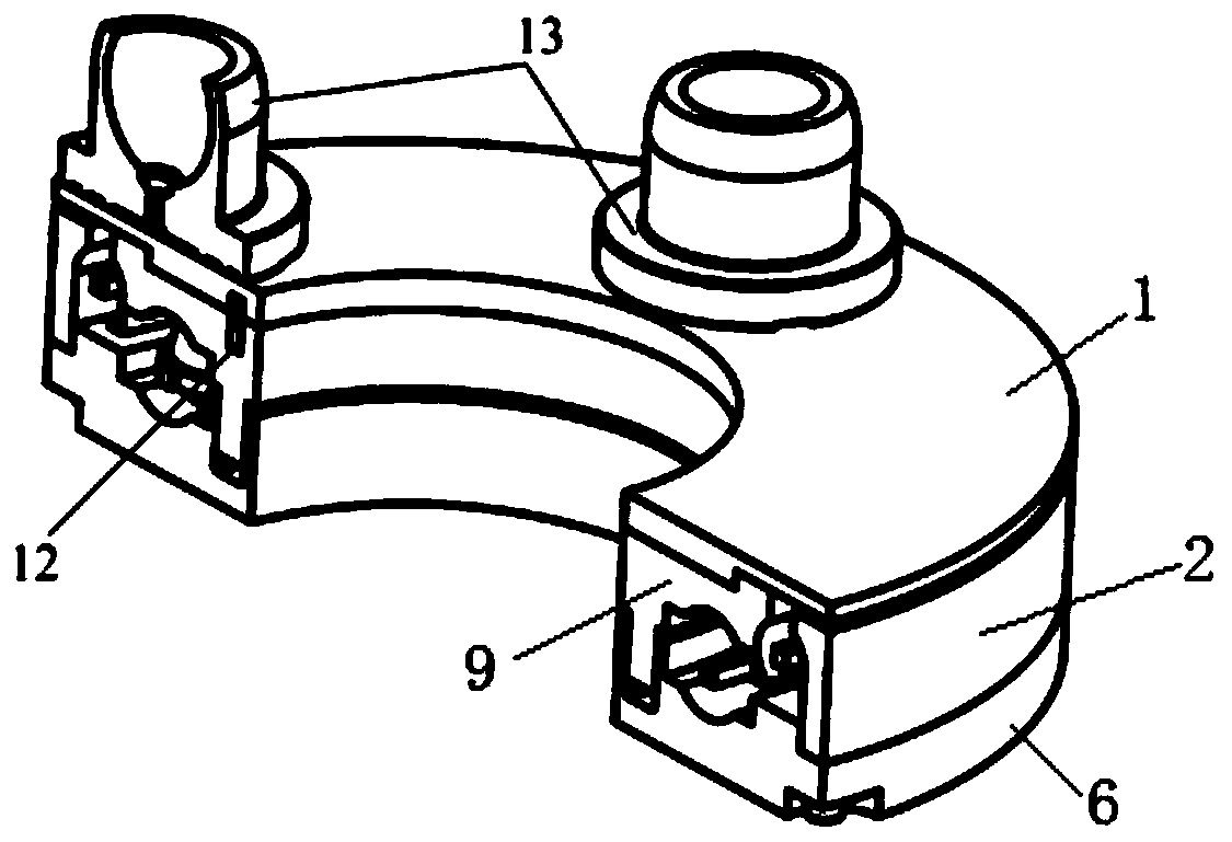
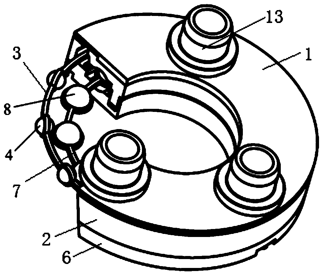
[0021] Such as figure 1 , 2 , 3 and 4, a swash plate hydraulic axial piston pump / motor heavy-duty slipper pair anti-friction disc is characterized in that it includes a rotating disc 1, a side cover 2, a base 6, an intermediate body 9, and a side 4 balls, 3 side cages, 8 bottom balls, 7 bottom cages. The rotating disk 1 is fixedly connected with the intermediate body 9 through pins 12 and interference fit. The side of the intermediate body 9 has a raceway for the side balls 4 to roll, and the bottom surface has a raceway for the bottom balls 8 to roll; the bottom ball 8 Installed between the raceway on the bottom surface of the intermediate body 9 and the raceway on the top surface of the base 6, the bottom surface cage 7 evenly separates the bottom surface balls 8 from each other, so that each bottom surface ball 8 is normally between the intermediate body 9 and the base 6 ground rolling; the side balls 4 are installed between the raceway of the side cover 2 and the side ra...


PUM


Abstract

The invention discloses a swash plate type hydraulic axial plunger pump / motor heavy-load sliding shoe pair friction-reducing disc in order to overcome technical defects of sliding shoe pairs. Slidingshoes slide freely on the outer surface of a rotating disc on the top of a friction-reducing disc body, or the sliding shoes are fixedly connected with the rotating disc; under driving of a friction force between the sliding shoes and the surface of the rotating disc, due to the support action of bottom balls and side balls, the rotating disc and an intermediate body rotate together with the sliding shoes, so that sliding movement between the sliding shoes in a sliding shoe pair and a swash plate surface is partially or completely converted into rolling movement between the side balls and thebottom balls, the relative movement speed between the sliding shoes and the rotating disc is also decreased at the same time, and thus the purpose of reducing the friction power loss of the sliding shoe pair is achieved. The friction-reducing disc is completely immersed in hydraulic oil during work for thorough lubrication and cooling, and since the bearing form of combined action of the balls andstatic pressure support is adopted, the friction-reducing disc can obtain a long service life through reasonable design and is also convenient to maintain and replace when worn.

Description

technical field [0001] The invention relates to the technical field of fluid transmission and control, in particular to a swash plate type hydraulic axial piston pump / motor heavy-duty sliding shoe pair anti-friction disc. Background technique [0002] Energy saving is a long-term development strategy for my country's sustainable development and a basic national policy of our country. The energy loss caused by friction is one of the main energy consumption methods in the equipment manufacturing industry. It is estimated that one-third of the world's total energy is consumed by one or more forms of friction. The Chinese Academy of Engineering Consulting Project Report released in 2009 pointed out that , through the correct use of tribology knowledge can save up to 327 billion yuan, accounting for 1.55% of GDP, so the energy-saving and environmental protection industry is still a strategic emerging industry that focuses on the development of my country's planning outline, and th...

Claims


Application Information

Patent Timeline
Patent Type & Authority Patents(China)
IPC IPC(8): F04B1/12F04B53/00F03C1/06
CPCF03C1/0602F04B1/122
Inventor 胡敏胡静王纯贤方素平曾亿山
Owner HEFEI UNIV OF TECH
Learn More