
Floating swash plate follower ball hinge conical plunger variable pump/motor rotation assembly

A technology of conical plunger and rotating components, applied in the direction of pumps, multi-cylinder pumps, machines/engines, etc., can solve the adverse effects of the overall transmission efficiency of the pump control transmission system, the large friction power loss between the plunger pair and the slipper pair, It has not completely solved the problems, so as to solve the problem of severe friction and wear, reduce frictional power loss, and facilitate maintenance and replacement.

Active Publication Date: 2021-11-12
HEFEI UNIV OF TECH
View PDF0 Cites 0 Cited by
  • Summary
  • Abstract
  • Description
  • Claims
  • Application Information

AI Technical Summary

Problems solved by technology

The long-term technical means to improve the anti-friction and anti-wear performance of the swash plate axial piston pump / motor plunger pair and the sliding shoe pair is based on the optimization design of the lubricating support structure, the surface modification of the friction interface and the surface microscopic modification technology, and has achieved Some important technological advances have not completely solved the problem. The friction and wear of the plunger pair and the sliding shoe pair and the failure of lubrication are still the most important technical problems restricting the performance of the swash plate axial piston pump / motor. Because the plunger The frictional power loss between the pair and the sliding shoe pair is large, resulting in low efficiency of the swash plate axial piston pump / motor under small displacement conditions, which adversely affects the overall transmission efficiency of the pump control transmission system

Method used


Image

  • Floating swash plate follower ball hinge conical plunger variable pump/motor rotation assembly
  • Floating swash plate follower ball hinge conical plunger variable pump/motor rotation assembly
  • Floating swash plate follower ball hinge conical plunger variable pump/motor rotation assembly

Examples


Embodiment Construction

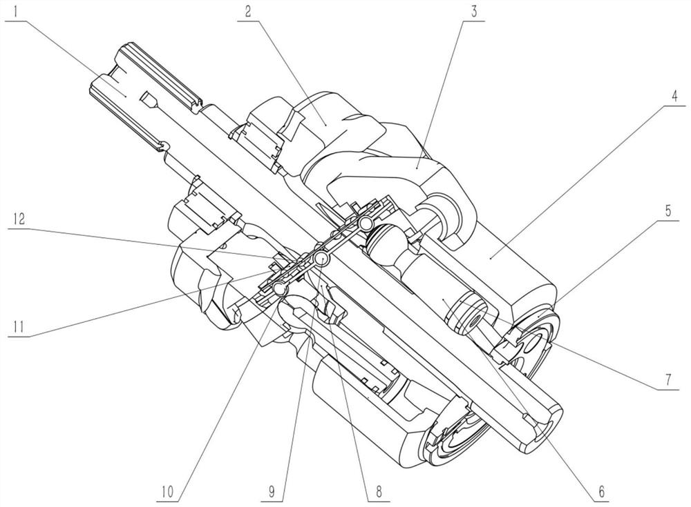
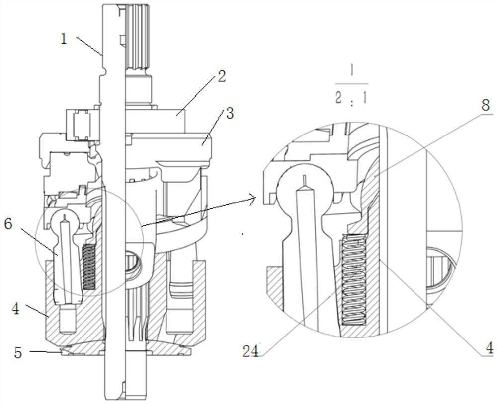
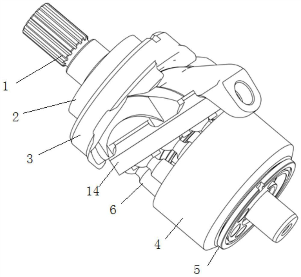
[0030] Such as figure 1 As shown, a through-shaft floating swash plate follower ball hinge joint tapered plunger variable pump / motor rotation assembly includes a floating swash plate assembly and a tapered plunger rotation assembly:

[0031] Such as Figure 5-10As shown, the design of the floating swash plate assembly is based on the special-shaped bearing structure formed by the cylindrical roller thrust bearing on the bottom surface and the angular contact ball bearing on the side surface, and is realized in the sealed space formed by the cooperation between the chassis 3 of the floating swash plate and the inner plate 15. The hydrostatic support structure together with the special-shaped bearing structure constitutes a hybrid support, which is characterized by: including inner disc 15, side balls 9, side cage 10, bottom roller 11, bottom cage 12, side cover 16 and floating swash plate chassis 3 The composition, applied to the swash plate axial piston pump / motor, can be use...


PUM


Abstract

The present invention disclosed a floating diagonal disk hinge hinge hinge hinge pump / motor rotation component, including floating diagonal and cone plunged rotation components.The front -end ball head and the rotating ball nest of the cone plunger are hinged. The back end only has the spherical area area and the pillar wall of the cylinder body.The principle of force solves the problem of friction and wear caused by the huge side force and torque caused by the traditional fixed oblique disk -type axial plunger pump.The inner plate of the floating diagonal disk is fixed with the rotating plate. The rotating disc is driven by the hinge of the cone -shaped plunger ball. Due to the support of the bottom roller and the side roller, the rotation disc and the inner disc renewal movement, so that the rotation and inner discs will turn around, thereby the rotation movement, thereby the rotation movement.The sliding movement of the original sliding boots and the sliding boots and the sliding boots and the slash plate converted into the rolling movement between the side roller and the bottom roller, which achieved the purpose of reducing the loss of the sub -friction power loss of heavy -duty skate boots.

Description

technical field [0001] The invention relates to the technical field of fluid transmission and control, and is applicable to a swash plate axial piston pump / motor, in particular to a floating swash plate follower ball hinge joint conical plunger variable displacement pump / motor rotary assembly. Background technique [0002] Due to its structural characteristics, the swash plate axial piston pump / motor is resistant to high pressure and can realize various variable functions, especially the displacement of the pump / motor can be easily controlled and adjusted, so that the output power of the pump / motor and the load Therefore, it has become the trump card component in hydraulic transmission technology. It has been widely used as the most important core power / executive component in hydraulic transmission system. It is a direct reflection of the development level and scientific and technological strength of a country's hydraulic component manufacturing. In the swash plate axial pis...

Claims


Application Information

Patent Timeline
Patent Type & Authority Patents(China)
IPC IPC(8): F04B1/22F04B1/2014F04B1/2085F04B1/2042F04B1/124
CPCF04B1/124F04B1/2014F04B1/2042F04B1/2085F04B1/22
Inventor 胡敏欧阳震奚光宇胡静曾亿山刘常海燕浩
Owner HEFEI UNIV OF TECH
Learn More