
Shaft seal

A shaft sealing and sealing lip technology, applied in the field of shaft sealing devices, can solve the problems of high power and loss, and achieve the effects of low friction power loss, small friction power loss, and reduced power loss

Inactive Publication Date: 2018-10-23
KACO
View PDF7 Cites 0 Cited by
  • Summary
  • Abstract
  • Description
  • Claims
  • Application Information

AI Technical Summary

Problems solved by technology

But this leads to high power losses due to high frictional losses

Method used


Image

  • Shaft seal
  • Shaft seal
  • Shaft seal

Examples


Embodiment Construction

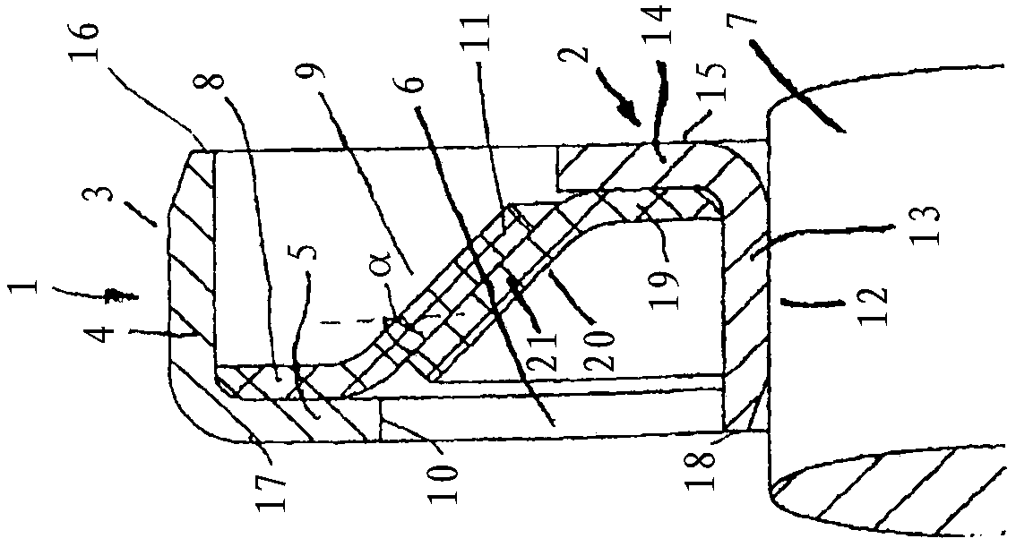
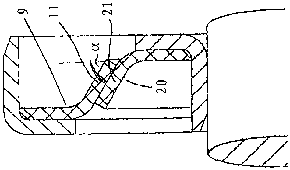
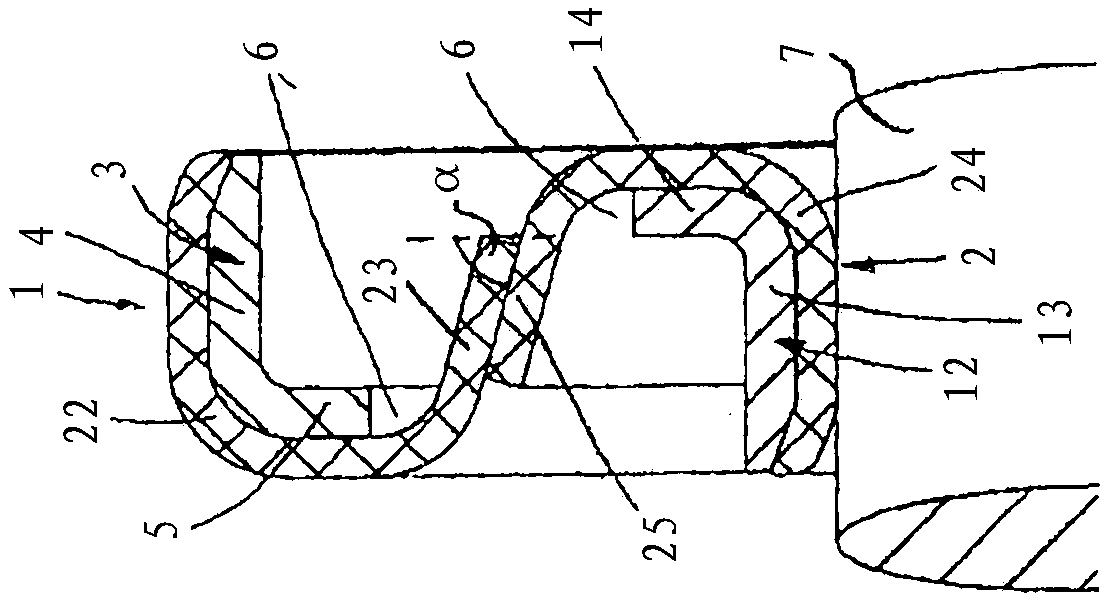
[0033] The outstanding feature of the shaft sealing device described below is that the shaft sealing device seals in contact in a dynamic state and has little friction on the sealing lip. The correspondingly designed shaft sealing device can be contactless when the rotation speed is high, and even at a very low rotation speed before lifting, the shaft sealing device has a very small frictional power loss. The shaft sealing device is constituted by two sealing units, which are arranged relative to each other such that the sealing parts of the sealing units are in contact with each other and in radial force and / or axial force. The sealing units are attached to each other. The dynamic sealing is no longer achieved by sealing the sealing element against the shaft, but by sealing the sealing element of one sealing unit against the sealing element of the other sealing unit.

[0034] figure 1 Shown is a shaft sealing device with two sealing units 1 and 2, which are each configured as ...


PUM


Abstract

The invention relates to a shaft seal having a rotationally fixed sealing unit (1, 2), which has at least one support (3, 12), to which at least one sealing element (9, 20) provided with a sealing part (11, 21) is fastened. The shaft seal has a second sealing unit (1, 2) that is to be rotationally fixed to a shaft (7) and that has at least one sealing element (9, 20). The at least one sealing element is fastened to a support (3, 12) and has a sealing part (11, 21). At least one of the sealing parts (11, 21) of the two sealing units (1, 2) contacts the sealing part (11, 21) of the respective other sealing unit (1, 2) under elastic pre-tension. Since the sealing part (11, 21) does not contact the shaft (7) in a sealing manner, only very low friction occurs on the sealing part (11, 21). The frictional power losses are consequently low.

Description

Technical field [0001] The invention relates to a shaft sealing device according to the preamble of claim 1. Background technique [0002] In order to seal the rotating shaft, shaft sealing devices in the form of radial shaft sealing devices are known. The shaft sealing device has a sealing disk as a sealing element, which bears sealingly against the shaft with a sealing lip. In order to ensure reliable dynamic sealing, the sealing lip must fit on the shaft with high radial force. But this leads to high power loss due to high friction loss. In most cases, hardened steel shafts are used as shafts. If the sealing lip is made of PTFE, in most cases a glass fiber composite material is required to keep the sealing lip less worn. The glass fibers contained in the composite material generate high friction losses on the shaft. Summary of the invention [0003] The object of the present invention is to configure the shaft sealing device of the type described in such a way that the fri...

Claims


Application Information

Patent Timeline
Patent Type & Authority Applications(China)
IPC IPC(8): F16J15/16F16J15/3228F16J15/3264
CPCF16J15/164F16J15/3228F16J15/3264
Inventor H·古斯特
Owner KACO
Learn More