
Rotary compressor

A technology of rotary compressors and rotors, which is applied in the direction of rotary piston machines, rotary piston pumps, mechanical equipment, etc., and can solve the problems of reciprocating compressors, such as difficulty in balancing the inertial force, short service life of wearing parts, and high processing accuracy. Achieve the effects of reduced friction and wear, reduced weight, and smooth machine operation

Active Publication Date: 2012-07-25
DAFENG FENGTAI FLUID MACHINERY TECHNOLOGY CO LTD
View PDF1 Cites 0 Cited by
  • Summary
  • Abstract
  • Description
  • Claims
  • Application Information

AI Technical Summary

Problems solved by technology

In addition, the reciprocating compressor is difficult to balance due to the inertial force of the movement, the vibration is large, the life of the wearing parts is short and the reliability is poor.
Scroll compressors and screw compressors are expensive due to their high machining accuracy and complex processes.

Method used


Image

  • Rotary compressor
  • Rotary compressor
  • Rotary compressor

Examples


no. 1 approach

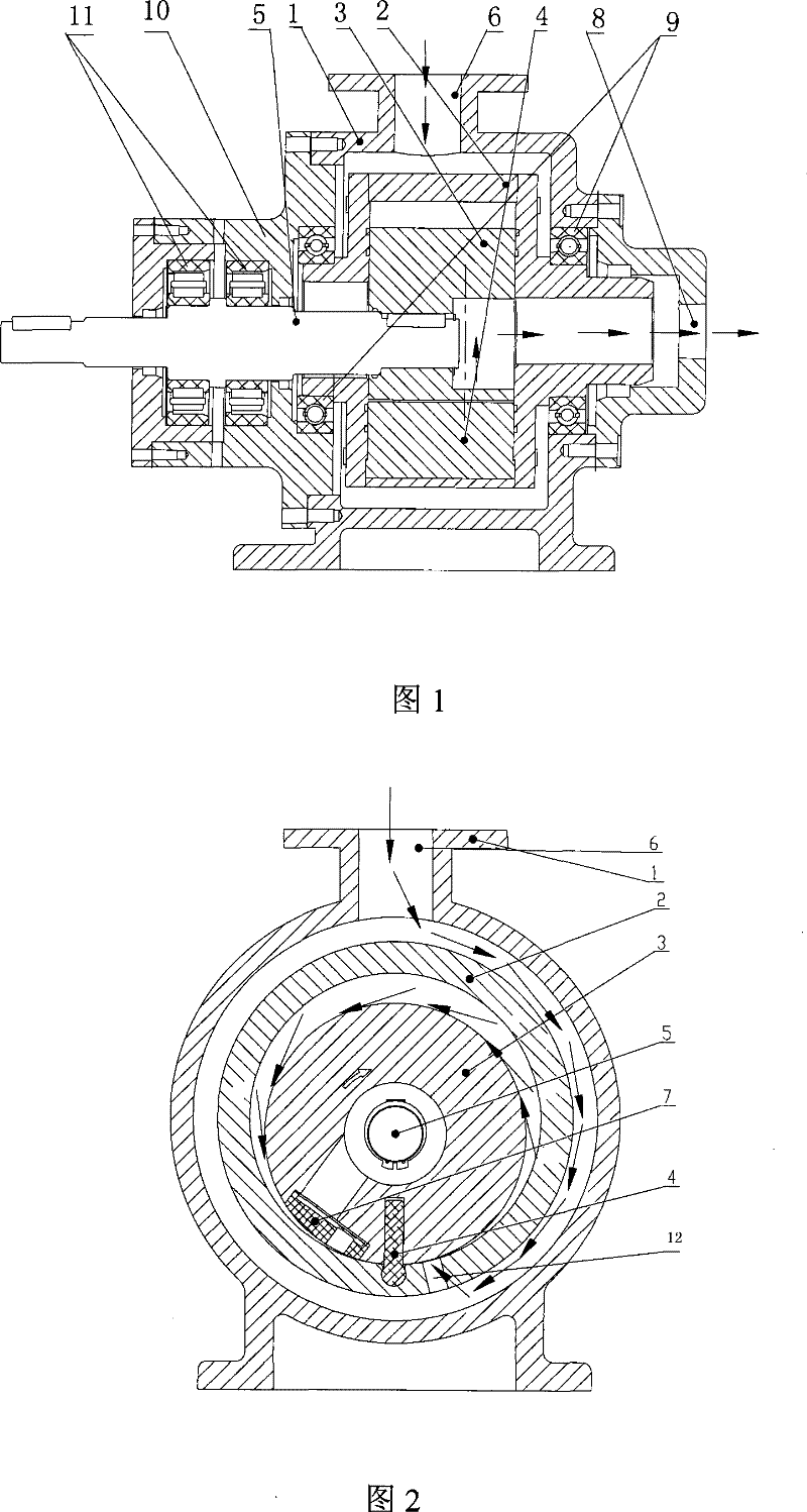
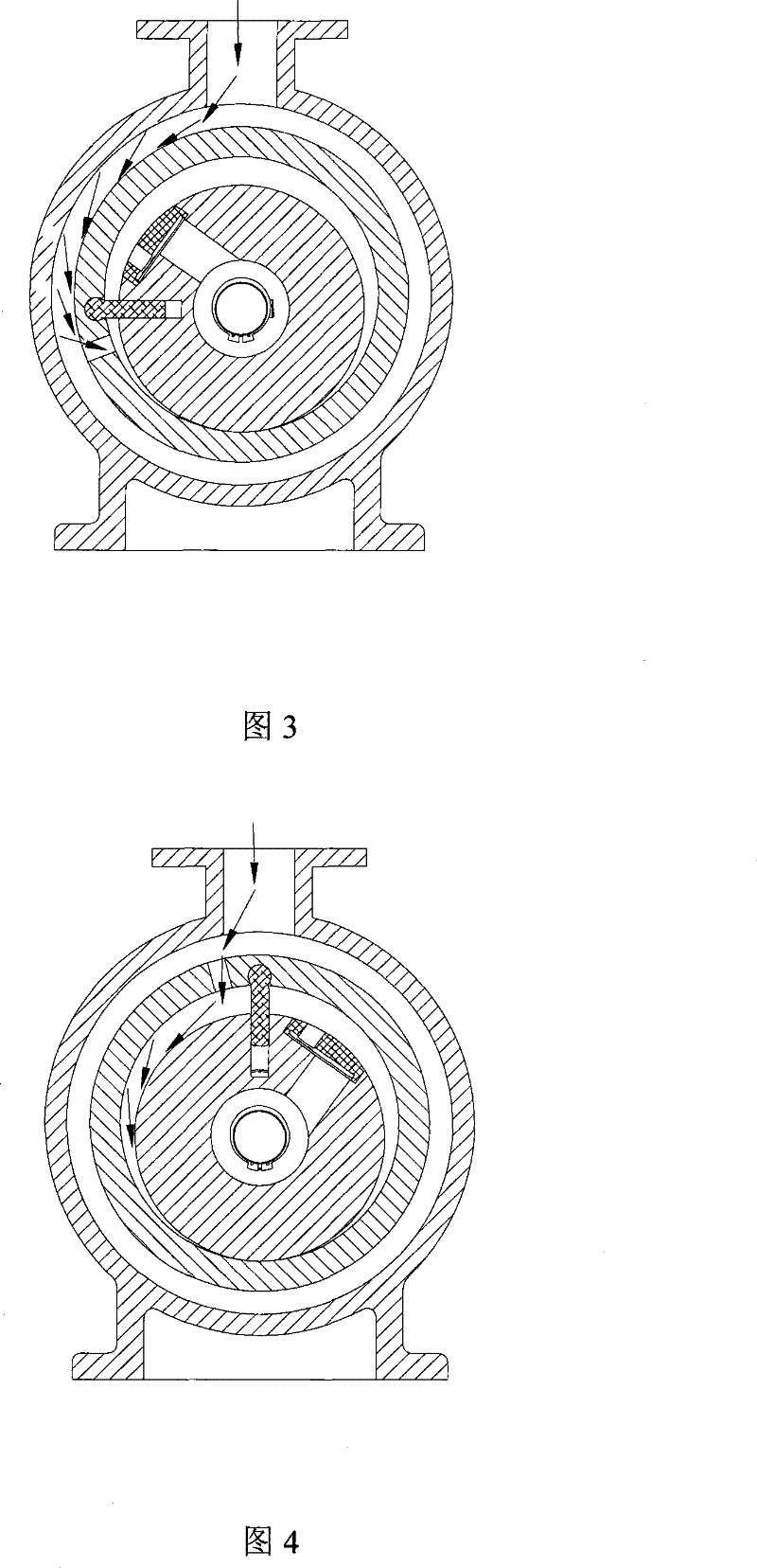
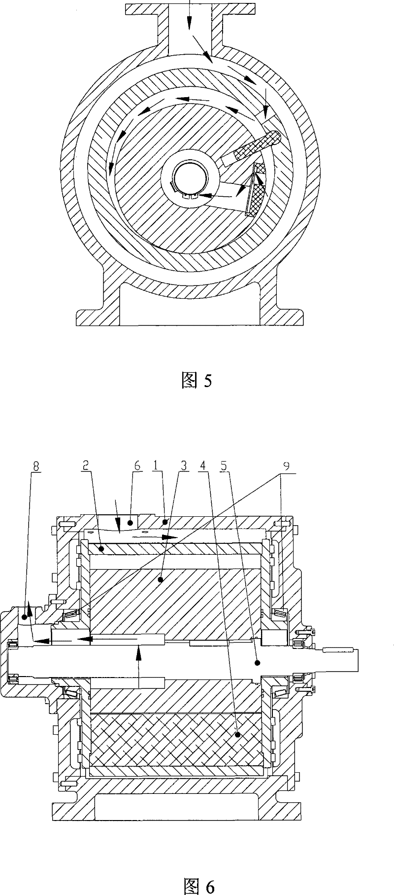
[0024] Such as Figure 1-2 As shown, the first embodiment of the rotary compressor of the present invention includes a casing 1, a cylinder body 2, a rotor 3, a slide plate 4, a main shaft 5, a suction port 6, an exhaust valve 7, an exhaust port 8, and a frame bearing 9. Eccentric seat 10, support bearing 11, cylinder air inlet 12.

[0025] The eccentric seat 10 is fastened together with the casing 1 by bolts, the main shaft 5 is cantilevered on the eccentric seat 10 through the support bearing 11, and the inner side end of the main shaft 5 is connected with the center shaft hole of the rotor 3 through a key and a keyway. That is, the rotor 3 rotates around the central axis of the main shaft 5 .

[0026] Both the cylinder body 2 and the casing 1 are in the shape of a cylinder, one side axial end of the cylinder body 2 is supported on the casing 1 through the frame bearing 9, and the other side axial end of the cylinder body 2 passes through the frame bearing 9 Support on the...


PUM


Abstract

The invention discloses a rotary type compressor which comprises a shell (1), a cylinder body (2), a rotor (3), a sliding plate (4) and an exhaust valve (7), wherein an air suction hole (6) and an exhaust hole (8) are arranged on the shell (1), rotating central axes of the cylinder body (2) and the rotor (3) are offset into a state that the outer circumferential surface of the rotor (3) is tangential with the inner circumferential surface of the cylinder body (2), the head of the sliding plate (4) is embedded into a cylinder of the cylinder body (2), the main body of the sliding plate (4) extends into a sliding plate groove of the rotor (3), the exhaust valve (7) is arranged on the outer circumference of the rotor (3) and the front of the rotating direction of the sliding plate (4), a cylinder body air inlet (12) which is positioned at the rear of the rotating direction of the sliding plate (4) is arranged on the cylinder body (2), and the sliding plate (4) and an internally tangent point are used for dividing crescent working volume between the inner circumferential surface of the cylinder body (2) and the outer circumferential surface of the rotor (3) into an air inlet cavity and an exhaust cavity.

Description

technical field [0001] The invention relates to an air compressor, a fluid conveying pump and a refrigeration air-conditioning compressor, in particular to a rotor and a cylinder synchronously rotating compression machine. Background technique [0002] Currently used compressors include reciprocating compressors, rolling rotor compressors, vane compressors, scroll compressors and screw compressors. Due to the inertial force that is difficult to balance, the reciprocating compressor has large vibration, low speed and large volume. In addition, there is a relatively high velocity of motion between the moving piston and the stationary cylinder body, and the friction and wear are serious. Secondly, the intake and exhaust valves, piston rings, etc. of this compressor are all vulnerable parts, which is also its fatal shortcoming, resulting in poor reliability and low efficiency of machine operation. The cylinder body of the rolling rotor compressor is stationary, and its meshing...

Claims


Application Information

Patent Timeline
Patent Type & Authority Patents(China)
IPC IPC(8): F04C18/46
Inventor 侯晓冬
Owner DAFENG FENGTAI FLUID MACHINERY TECHNOLOGY CO LTD
Learn More