Anti-knock protector
A technology of protectors and supports, which is applied in the direction of emergency protection devices, circuits, electrical components, etc., can solve the problems of affecting the anti-explosion ability of protectors, the huge explosion impact force of the melt, and the increase of fusing time, so as to save costs and distance The effect of uniformity, longitude, and length reduction
- Summary
- Abstract
- Description
- Claims
- Application Information
AI Technical Summary
Problems solved by technology
Method used
Image

Examples
Embodiment 1
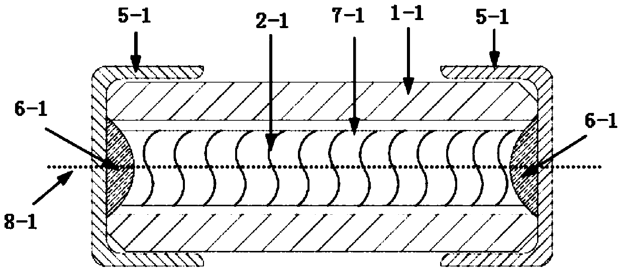
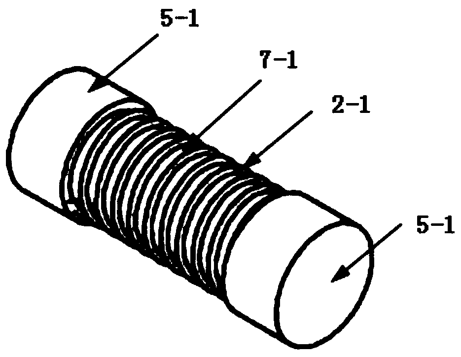
[0044] The melt 2 in this embodiment is formed by helically coiling more than two resistance wires, and the support body 3 passes through the gap between the helically coiled resistance wires. Such as image 3 and Figure 4 As shown, taking two resistance wires as an example, they are coiled into a twisted shape to form a melt 2, and the two ends of the resistance wires 2a and 2b are connected to the electrode 5 and are electrically connected with it through solder 6. The resistance wires 2a and 2b It can be the same material or different materials, and it can be selected according to the requirements such as fusing time in the circuit used by the protector. Since a gap must be formed between the two resistance wires during the coiling process, the gap is passed by the support body 3 .
[0045] In order to enable the support body 3 to be firmly arranged between the two resistance wires, when making the anti-knock protector device, the resistance wire 2a is first placed, and se...
Embodiment 2
[0054] Such as Figure 6 As shown, the difference from Embodiment 1 is that the support body 3 in this embodiment is a bundle of glass fiber wires, which are twisted and spirally coiled on two resistance wires, and the support body 3 is clamped and fixed to the melt by the two resistance wires. 2, a certain angle is formed between multiple glass fiber lines, and the angles between them and the axial direction are different, but at least one glass fiber is set along the direction perpendicular to the center line of the two electrodes, and the remaining glass fibers The angle between the fiber and the axial direction can be 30-150°. In actual use, such a support body 3 can still provide radial support for the melt 2, so that the melt 2 and the inner wall of the shell 1 have a certain effect of distance.
[0055] Same as the first embodiment, as long as the glass fiber bundle can provide the melt 2 with a support force perpendicular to the inner wall of the housing 1 when the gl...
Embodiment 3
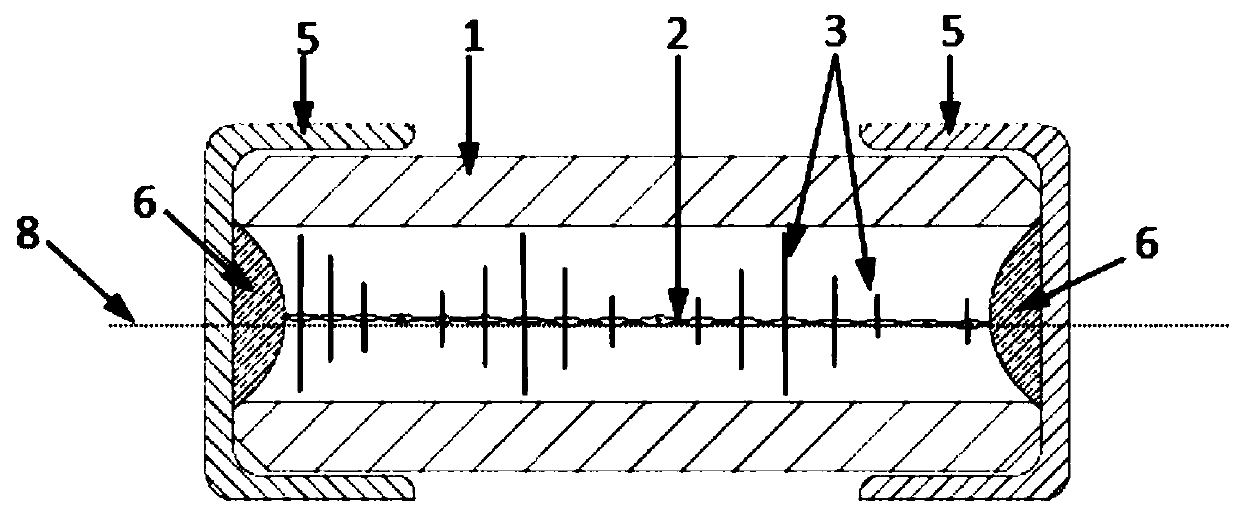
[0057] Different from Example 1, such as Figure 7 As shown, the support body 3 in this embodiment does not pass through the melt 2 , but for the support body 3 arranged in the radial direction, the melt 2 is wound along the circumferential direction of the support body 3 . This embodiment is not only applicable to the situation where the melt 2 is only one resistance wire, but also applicable to the situation where many resistance wires are bundled or several resistance wires in Embodiment 1 are wound to form a melt.
[0058] Based on the anti-knock protector device described in this embodiment, in order to facilitate the combination of the melt 2 and the support body 3 to slide down in the housing 1 during use, the length of the support body 3 should not be greater than the inner diameter of the housing 1 . However, the length of the support body 3 should not be too small (too small will cause the melt 2 to contact the pipe wall under the action of pressure), usually the val...
PUM
 Abstract
Description
Claims
Application Information