3D folding printer

A printer, 3D technology, applied in 3D object support structures, metal processing equipment, manufacturing tools, etc., can solve the problems of rough wiring, static interference, inaccurate transmission system, etc., to increase the overall aesthetics and reduce the three-dimensional Space, the effect of reducing errors

Inactive Publication Date: 2017-04-19
郝明仲
View PDF5 Cites 5 Cited by
  • Summary
  • Abstract
  • Description
  • Claims
  • Application Information

AI Technical Summary

Problems solved by technology

[0004] 1. The longer the printing time, the friction between the synchronous belt and the synchronous wheel will expand due to heat, resulting in deformation of the tooth shape, the longer the synchronous belt, the larger the gap between the tooth shapes, and the phenomenon of lost steps and wrong steps will increase the transmission error;
[0005] 2. The material of the synchronous belt is mostly rubber, which is highly elastic. It meshes with the synchronous wheel in a tooth shape. The tooth gap is large, and the teeth are mostly jagged, and the vibration is large during transmission;
With the increase of printing speed, the torque of small power stepping motor decreases, which is almost 0, and it cannot accurately provide transmission force for the transmission system
Moreover, this kind of stepper motor is mostly open-loop control, which cannot adapt to the rapid acceleration and rapid deceleration during the printing process, and it is easy to lose steps and wrong steps;
[0007] 4. Most of the existing printers have relatively rough wiring, and most of them are exposed wiring. During the printing process, it is easy to interfere with the workbench, or even be directly broken by moving parts such as the workbench.
In addition, long-term exposed cables are likely to cause oxidation of the cables, static interference, etc., and the exposed cables reduce the design aesthetics of the equipment
[0008] 5. The space utilization rate of most printers is low, and the whole body is mostly composed of a large machine box, which is very heavy and not easy to move

Method used


Image

  • 3D folding printer
  • 3D folding printer

Examples


Embodiment Construction

[0023] The present invention will be further described below in combination with specific embodiments.

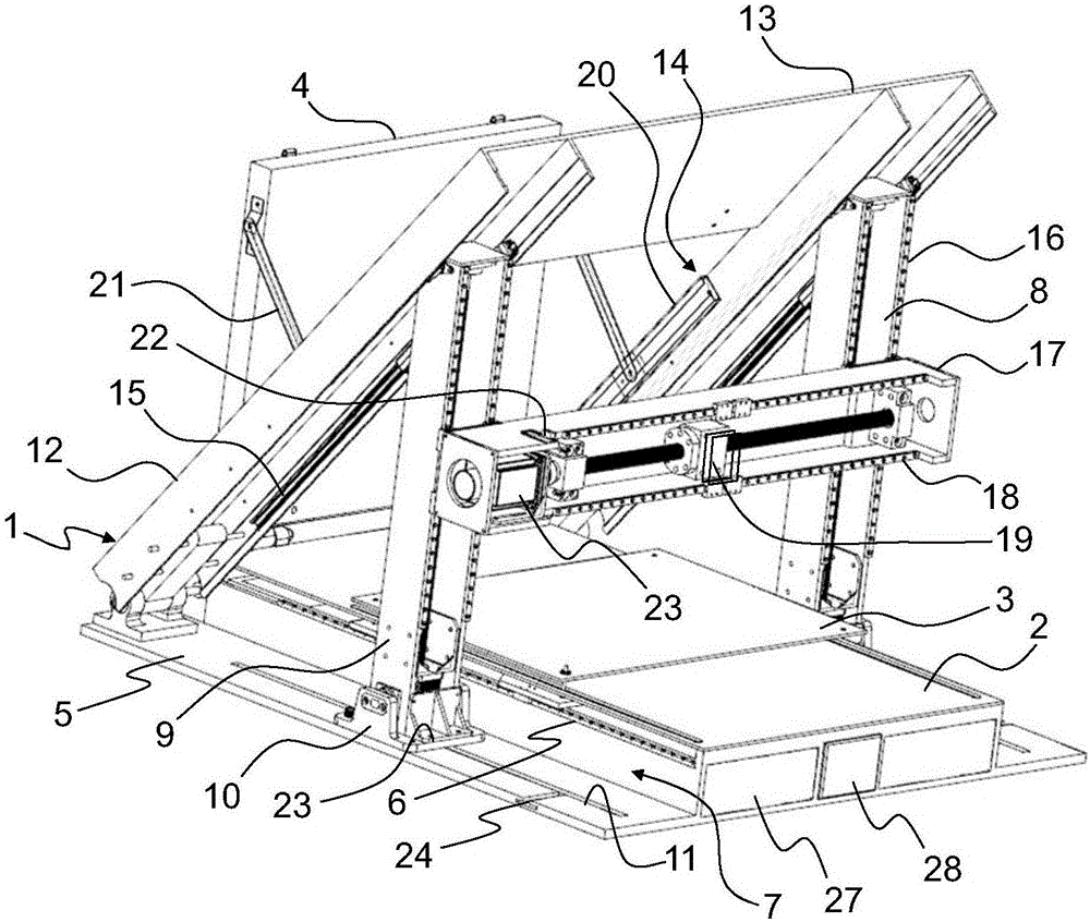
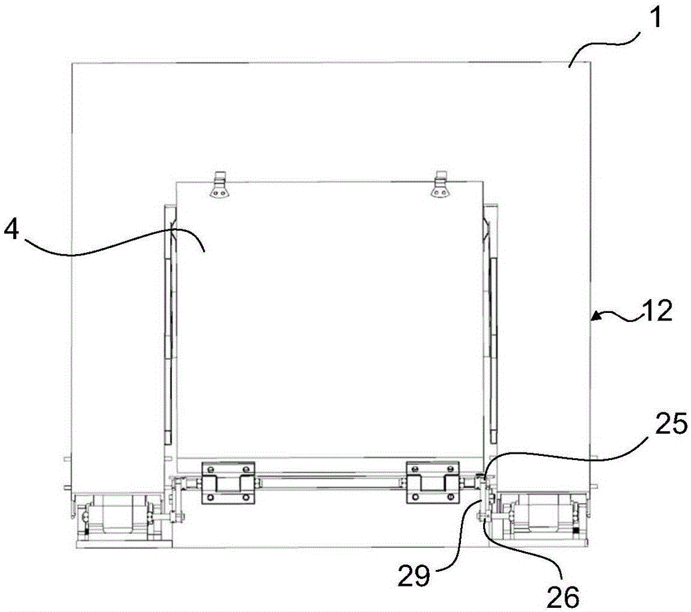
[0024] like figure 1 , figure 2 As shown, a 3D folding printer includes an upper cover 1, a base 2, a workbench 3, a main board 4 and a lower cover 5, the base 2 is located in the middle of the lower cover 5, the inner side of the base 2 is hinged with a main board 4, and the base 2 There is a first slide rail 6 extending along the X-axis direction, the first slide rail 6 is connected with the worktable 3 on the surface of the base 2, and the precise control between the workbench 3 and the base 2 is realized through motor and screw drive.

[0025] Both sides of the base 2 form a group of semi-open first accommodation spaces 7 on the lower cover plate 5, and a column 8 is respectively arranged on both sides of the base 2. The column 8 includes a hinged column 9 and a sliding seat 10, and the sliding seat is located on In the chute 11 of lower cover plate 5 surfaces, lower...


PUM


Abstract

The invention discloses a 3D folding printer, and belongs to the field of 3D printing equipment. The 3D folding printer is provided with an upper cover, a base, a worktable, a main machine board and a lower cover plate. In combination with a stand column, a concentric-square-shaped beamand a plurality of sets of sliding rails, when the upper cover and the lower cover plate are closed, X, Y and Z-axis moving structures of the 3D printer can be completely contained in a flat space and the3D folding printer is convenient to carry. According to the transmission design of the printer, a lead screw is matched with the sliding rails to carry out transmission, the structure defects of printers on the market are avoided, the structure is firm, vibration is eliminated, and errors are reduced.

Description

technical field [0001] The invention relates to the field of 3D printer equipment, in particular to a 3D folding printer. Background technique [0002] There are many similar 3D printers on the market today. The features of these printers are almost identical, and the structural forms of printers sold on the market are mainly divided into three categories: 1. makerbot type; 2. cross XYZ type; 3. gantry type. These devices obtain the tool path trajectory of the cross-sectional profile of each layer by slicing the 3D model in the Z-axis direction. Then the gcode language is decoded through the main board of the printer, and the structure is based on the principle of three-axis linkage, and the transmission commands of the X, Y, and Z axes are transmitted to the motors of each axis to control the movement of the motors. The rotary motion of the motor is transmitted to the entire transmission system of the printer. [0003] The transmission of traditional 3D printers is drive...

Claims


Application Information

Patent Timeline
Patent Type & Authority Applications(China)
IPC IPC(8): B29C64/232B29C64/236B33Y30/00
CPCB33Y30/00
Inventor 郝明仲孙玉文夏明宏
Owner 郝明仲
Why Eureka
Try Eureka