Damping connection structure for fire wheel

A vibrating connection, hot wheel technology, applied in the direction of roller skates, skateboards, skating, etc., can solve the problems of lack of firmness, no protective structure, discomfort in the user's legs, etc., to achieve the effect of improving sports experience, simple structure, Ease of promotion

Pending Publication Date: 2017-04-26
XUZHOU BLUE LAKE INFORMATION TECH CO LTD
View PDF0 Cites 0 Cited by
  • Summary
  • Abstract
  • Description
  • Claims
  • Application Information

AI Technical Summary

Problems solved by technology

[0002] For another invention patent of the applicant, a hot wheel, its structure is that the support part is fixed on one side of the moving wheel through the rotating shaft, and the pedal is fixed on the support part, and the left and right feet are used to pedal laterally The moving wheel achieves the purpose of moving forward. Since the operator needs to push the left and right feet sideways during use, if the supporting part is directly connected to the rotating shaft on the moving wheel, when in use, the rotating shaft and The support part is in a hard connection, and if the force on the rotating shaft is too large, if it is more violent, it will cause the shaft to break, and the connection with the support part will easily become loose. The supporting parts of the user will press the user's left and right legs when pushing the moving wheel sideways, which will cause discomfort in the user's legs and affect the sports experience of the Hot Wheels. However, the elastic supporting parts will be incompatible with The inner side of the moving wheel is rubbed and damaged, which affects the normal use of the hot wheel
And in the process of use, there is no protective structure on the moving wheel, and it is easy to cause damage to the user when falling down. In the original design, the supporting part is directly fixed on one side of the moving wheel through the rotating shaft. Therefore, the protective shell is directly installed on the outer rotating shaft of the moving wheel, which is not firm, and also affects the use

Method used


Image

  • Damping connection structure for fire wheel

Examples


Embodiment Construction

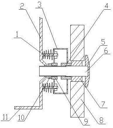
[0014] A vibration-damping connection structure for hot wheels of the present invention is realized in this way. When in use, both feet step on the pedal (11), and the legs are attached to the supporting part (2). When sliding, the pedals facing the ground, there will be a side pressure on the supporting part (2), and the supporting part (2) will press the two damping parts (1) sideways, and the two fixed shafts will slide along the frame part (3) respectively, The compression springs on the two fixed shafts are compressed to consume a certain amount of vibration force for vibration reduction. The bearing (7) is designed between the moving wheel (8) and the rotating shaft (6), which can prevent the moving wheel ( 8) When rotating, it drives the shaft (6) to rotate, and the design of one end of the support sleeve (4) in contact with the bearing (7) can fix the bearing (7), and the inner wall of the other end of the support sleeve (4) is set The threaded design enables the suppo...


PUM


Abstract

The invention discloses a damping connection structure for a fire wheel. The damping connection structure is a connection device for damping in movement. When a person treads two mobile wheels respectively by left and right feet and moves, the damping connection structure improves movement experience. The damping connection structure is characterized in that a support part is connected to the mobile wheel through a rotation shaft, the support part is located at one side of the mobile wheel, a pedal is arranged at one side of the mobile wheel, the bottom of the pedal is located under the center of the rotation shaft, a bearing is arranged between the mobile wheel and the rotation shaft, the support part has a bent plate structure and is prepared from an elastic material, the middle of a frame part is connected to the rotation shaft, the frame part is located between the mobile wheel and the support part, a support sleeve and a fixing sleeve are arranged between the frame part and the rotation shaft, one end of the support sleeve contacts with the bearing, the inner wall of the other end of the support sleeve is provided with threads, the fixing sleeve is fixed by a fixing nut and the frame part and the support part are fixedly connected directly through two damping parts.

Description

technical field [0001] The invention relates to a vibration-damping connection structure for a hot wheel, relates to a vibration-damping connection structure used on a hot wheel, and belongs to the field of entertainment facilities. In particular, it relates to a vibration-absorbing connection structure capable of improving the sports experience of Hot Wheels. Background technique [0002] For another invention patent of the applicant, a hot wheel, its structure is that the support part is fixed on one side of the moving wheel through the rotating shaft, and the pedal is fixed on the support part, and the left and right feet are used to pedal laterally The moving wheel achieves the purpose of moving forward. Since the operator needs to push the left and right feet sideways during use, if the supporting part is directly connected to the rotating shaft on the moving wheel, when in use, the rotating shaft and The support part is in a hard connection, and if the force on the ro...

Claims


Application Information

Patent Timeline
Patent Type & Authority Applications(China)
IPC IPC(8): A63C17/08A63C17/22A63C17/14
CPCA63C17/08A63C17/14A63C17/22
Inventor 不公告发明人
Owner XUZHOU BLUE LAKE INFORMATION TECH CO LTD
Why Eureka
Try Eureka