Residual quantity-reducing member

一种残量、部件的技术,应用在残量减少部件领域,能够解决无法内容物排出量稳定化、内装袋排出量无法稳定化、无法稳定地获得混合比等问题,达到减少残存量、形状简单、排出量稳定的效果

Active Publication Date: 2017-05-10
TOYO AEROSOL IND CO LTD
View PDF11 Cites 7 Cited by
  • Summary
  • Abstract
  • Description
  • Claims
  • Application Information

AI Technical Summary

Problems solved by technology

[0026] Even when such a flow path R is tightly pasted with the inner bag, the minimum space is secured and the flow path R is not closed until the end, but the flow path resistance is large, and there is a change in the state of the inner bag during discharge. Furthermore, the flow path resistance may also change significantly.
[0027] In this way, although the contents are smoothly discharged until the end and the remaining amount can be sufficiently reduced, there are various conditions such as the storage state of the flexible inner bag, the material, and the viscosity of the contents, and it is impossible to reduce the contents per unit time. Possibility of stabilizing discharge volume
[0028] And, if Figure 14 As shown in (a), when applied to an aerosol container configured by arranging a plurality of flexible inner bags in one outer tank so as to accommodate different types of contents without mixing them and discharge them simultaneously, each inner bag The discharge amount per unit time of the bag cannot be stabilized, and there is a possibility that the desired mixing ratio cannot be obtained stably

Method used


Image

  • Residual quantity-reducing member
  • Residual quantity-reducing member
  • Residual quantity-reducing member

Examples


Embodiment 1

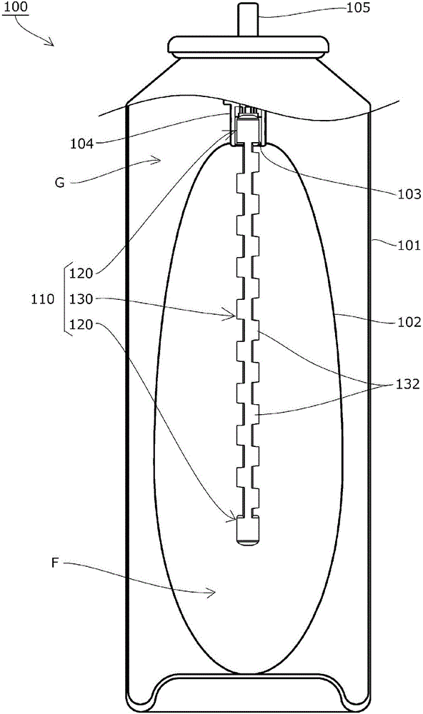
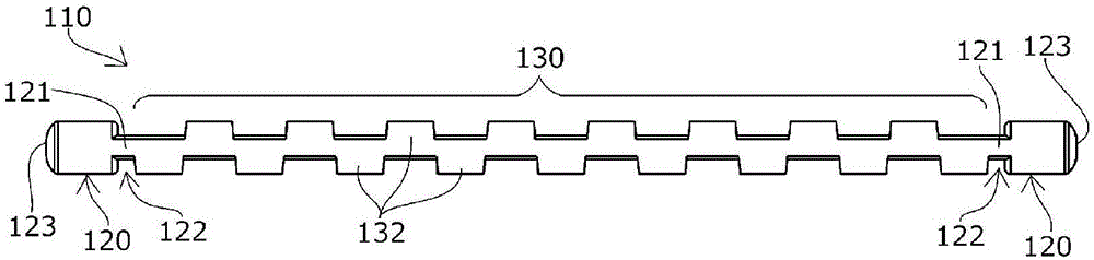
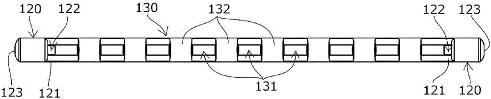
[0062] The remaining amount reducing member 110 according to the first embodiment of the present invention is inserted into the inflow port 103 of the aerosol container 100 similar to the above-mentioned known aerosol container 500 instead of the known dipping tube 511 .

[0063] That is, if figure 1 As shown, the inside of the outer tank 101 of the aerosol container 100 is provided with an inner bag 102 containing the contents F, and the inner bag 102 is provided with a spout 104, and the top of the inner bag 102 has a rod 105, and the inner bag 102 There is an inflow port 103 in the inner opening.

[0064] The space between the outer tank 101 and the inner bag 102 of the aerosol container 100 is filled with a pressurized fluid G such as nitrogen gas, and when the lever 105 is pressed, the contents contained in the inner bag 102 flow in from the inflow port 103, and are discharged from the inner bag 102. The front end of the rod 105 is discharged to the outside.

[0065] F...

Embodiment 2

[0092] The remaining amount reducing member 210 of the second embodiment of the present invention is as Figure 9 to Figure 12 As shown, in addition to the structure of the remaining amount reducing member 110 of the first embodiment described above, two outer surface grooves 238 extending in the longitudinal direction are provided on the arcuate surface 233 at the arc of the adjacent grooved block 232 . A position where the surface 233 does not overlap in the longitudinal direction (The same structure as that of the first embodiment is shown with reference numerals corresponding to No. 200, and description of the structure is omitted.).

[0093] Outer surface groove 238 such as Figure 12 As shown in (b), two arcuate surfaces 233 of each grooved block 232 are provided so as to extend in the longitudinal direction.

[0094] In this embodiment, it is formed at the position and cross-sectional shape at the maximum that does not overlap with the arcuate surface 233d of the adjac...


PUM


Abstract

The present invention provides a residual quantity-reducing member, which: reduces the final residual amount of contents to be discharged by preventing the occurrence of spaces, the perimeter of which is blocked by a pressurized fluid; stabilizes the amount of contents discharged per unit time; and makes it possible to discharge the contents smoothly to the end. Inside a flexible inner bag (102) that is disposed in an aerosol container (100), a residual quantity-reducing member (110) for reducing the final residual amount of contents (F) to be discharged is installed. The residual quantity-reducing member (110) is provided with a mounting part (120) that is mounted on an inflow port (103) of the inner bag (102) so as to allow inflow of the contents F, and a guide part (130) obtained by connecting multiple grooved blocks (132), which have a longitudinal guiding groove (131), in a row in the longitudinal direction.

Description

technical field [0001] The present invention relates to a remaining amount reducing member attached to the inside of a flexible inner bag disposed inside an aerosol container to reduce the final remaining amount of discharged contents. Background technique [0002] There is known an aerosol container which is configured by arranging and integrating a flexible inner bag inside an outer can, storing the contents to be discharged in the inner bag, and filling and pressurizing the space between the inner bag and the outer can. The fluid presses the flexible inner bag, and the contents accommodated in the inner bag are discharged from the inlet to the outside (for example, refer to Patent Document 1, etc.). [0003] In such an aerosol container, since the contents do not come into contact with the pressurized fluid, any pressurized fluid can be used, and since the pressurized fluid is not discharged together with the contents, the contents can be efficiently discharged. [0004]...

Claims


Application Information

Patent Timeline
Patent Type & Authority Applications(China)
IPC IPC(8): B65D83/62
CPCB65D83/62B65D83/32B65D83/68B65D1/323
Inventor 尾形谦
Owner TOYO AEROSOL IND CO LTD
Why Eureka
Try Eureka