
Experimental apparatus for testing shear stress of cell fluid
A fluid shearing, experimental device technology, applied in biochemical cleaning devices, enzymology/microbiology devices, bioreactors/fermenters for specific purposes, etc., can solve devices or systems without multi-channel fluid shear stress , Inability to implement precise control, simple loading device and other problems, to achieve the effects of novel design, simple structure, average and effective loading force
- Summary
- Abstract
- Description
- Claims
- Application Information
AI Technical Summary
Problems solved by technology
Method used
Image

Examples
Embodiment 1
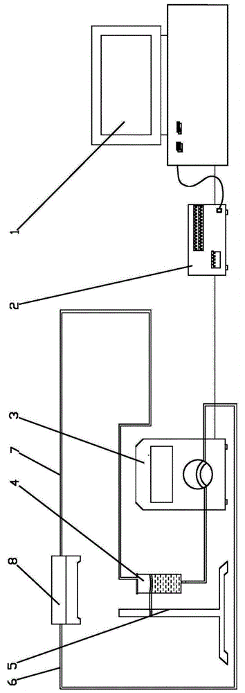
[0020] An experimental device for testing cell fluid shear stress, including a host computer 1, a pump controller 2, a peristaltic pump 3, a liquid storage tank 4, a bracket 5, an outlet pipe 6, a return pipe 7, and a fluid chamber 8.
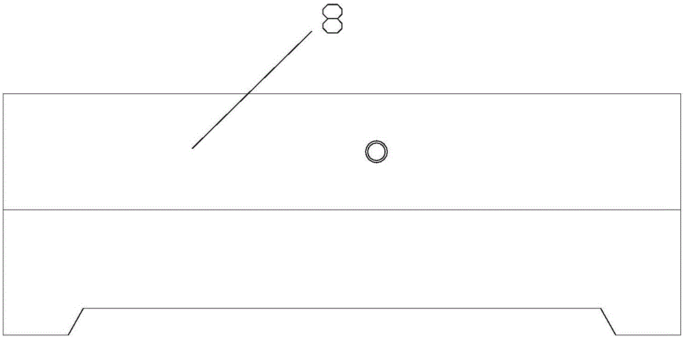
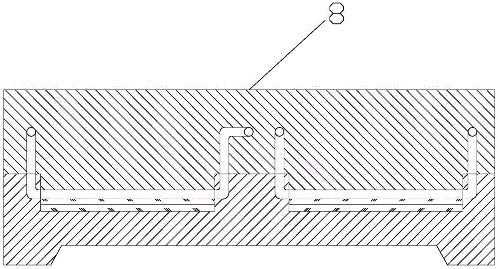
[0021] Such as Figure 1 to Figure 8 As shown, the pump controller 2 is respectively connected with the upper computer 1 and the peristaltic pump 3, and the liquid storage tank 4 is installed on the bracket 5. The upper part of the liquid storage tank 4 is provided with a water return port, and the lower part is provided with a water outlet. One end of 8 is provided with an inlet, and the other end is provided with an outlet. One end of the outlet pipe 6 is connected to the outlet of the liquid storage tank 4, and the other end is connected to the inlet of the fluid chamber 8 through the pump head of the peristaltic pump 3. One end of the return pipe 7 is connected with the outlet of the fluid chamber 8, and the other end is connected with the ...
PUM
| Property | Measurement | Unit |
|---|---|---|
| diameter | aaaaa | aaaaa |
| diameter | aaaaa | aaaaa |
Abstract
Description
Claims
Application Information