
Fan

A fan and impeller technology, applied in the field of household fans, can solve the problems of low airflow transmission efficiency and poor sealing performance in the fan

Inactive Publication Date: 2017-05-24
许彐琼
View PDF5 Cites 0 Cited by
  • Summary
  • Abstract
  • Description
  • Claims
  • Application Information

AI Technical Summary

Problems solved by technology

However, the sealing performance between the impeller housing and the shroud of the im

Method used


Image

  • Fan
  • Fan
  • Fan

Examples


Embodiment Construction

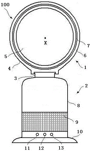
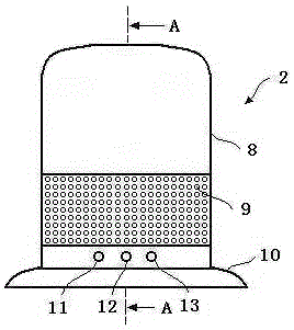
[0030] Figure 1 is a schematic view of the fan of the present invention viewed from the front of the device, from figure 1 It can be seen that the fan 100 includes a base 2 and a nozzle 1 disposed on the base 2 . The base 2 includes a base 10 and a base 8 positioned on the base 10. The base 8 includes an air inlet 9 and a plurality of buttons 11, 12 and 13 operable by the user. The air inlet 9 is formed in a plurality of holes formed on the base outer shell. form. Air outside the fan is drawn into the base 8 through the air inlet 9 .

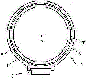
[0031] figure 2 Is a schematic diagram of the nozzle of the fan shown in Figure l. From figure 2 As can be seen in the figure, the nozzle 1 comprises a main body 4 and an inlet portion 3 . The main body 4 includes an outer shell 6, an internal channel for receiving airflow, an air outlet 7 for emitting airflow, and an opening for allowing the inlet part 3 to partially protrude. In this embodiment, the main body 4 can slide relative to th...


PUM

PropertyMeasurementUnit
Depthaaaaaaaaaa
Widthaaaaaaaaaa

Abstract

The invention relates to a fan. The fan comprises a base and a nozzle, the base comprises a vane wheel shell, a vane wheel and a motor, wherein the vane wheel is located in the vane wheel shell, and the motor is used for rotating the vane wheel around a rotating shaft. The vane wheel comprises a wheel hub, a plurality of blades connected to the wheel hub and a shield surrounding the wheel hub and the blades. The fan is characterized in that one of the vane wheel shell and the shield includes a first groove, and the other one of the vane wheel shell and the shield comprises a first convex body, part of the first convex body is located in the first groove, and the depth direction of the first groove is parallel or perpendicular to the direction of the rotating shaft. The fan can improve transferring efficiency of airflows.

Description

technical field [0001] The invention relates to a fan. In particular, but not exclusively, the present invention relates to domestic fans, such as desk fans, for use in generating air circulation and air flow in a room, office or other domestic environment. Background technique [0002] A traditional household fan generally includes a blade set that rotates around a rotating shaft and a motor that drives the blade set to rotate. The movement and circulation of the air stream creates "wind cooling", which cools the user as heat is dissipated by convection and evaporation. [0003] Fans are available in a variety of sizes and shapes. Ceiling fans are usually larger than lm in diameter and are usually mounted in a suspended manner from the ceiling to provide downward airflow to cool the room. Desk fans are usually free to place and portable. Tower fans typically include an elongated, vertically extending housing that houses a set of blades for creating airflow, using an osc...

Claims


Application Information

Patent Timeline
IPC IPC(8): F04D25/08F04D29/66F04D29/26F04D29/40F04B41/06F04F5/46
CPCF04B41/06F04D25/0606F04D25/08F04D29/26F04D29/403F04D29/664F04D29/668F04F5/46
Inventor 任文华
Owner 许彐琼
Learn More