Power allocation method for marine DC power generation equipment based on droop characteristics

A power generation equipment and DC power generation technology, which is applied in the direction of parallel operation of DC power supplies, DC network circuit devices, electrical components, etc., can solve problems such as system reliability reduction, achieve simple implementation methods, solve system reliability reduction, and realize self-adaptation sexual effect

Active Publication Date: 2019-04-05
SHANGHAI QIYAO HEAVY IND CO LTD
View PDF5 Cites 0 Cited by
  • Summary
  • Abstract
  • Description
  • Claims
  • Application Information

AI Technical Summary

Problems solved by technology

Common parallel current sharing technologies with interconnection lines include master-slave setting method, average current method, maximum current method, etc. Parallel connection technology with interconnection lines belongs to centralized control. This control method can provide better power quality and make distributed generation more efficient. Maximization, but also brings some limitations, such as high reliance on fast and reliable communication systems, reduced system reliability by introducing communication circuits and central controllers, etc.
The existing non-interconnection control technology is mainly the droop characteristic adjustment method, which can effectively balance the load based on the droop characteristic. However, the traditional droop characteristic is highly dependent on the line parameters between the DC grid and the load. When encountering the DC grid When disturbed, it will not be possible to obtain accurate power distribution through traditional droop controllers

Method used


Image

  • Power allocation method for marine DC power generation equipment based on droop characteristics
  • Power allocation method for marine DC power generation equipment based on droop characteristics
  • Power allocation method for marine DC power generation equipment based on droop characteristics

Examples


Embodiment Construction

[0020] The present invention will be described in detail below with reference to the drawings and specific embodiments.

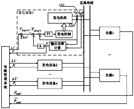
[0021] figure 1 It is a schematic diagram of the principle of a marine DC power grid according to an embodiment of the present invention. Such as figure 1 As shown, the marine DC power grid includes a power management system, multiple power generation equipment, a DC bus, and multiple loads. The output ends of the power management system are respectively connected to the input ends of multiple power generation equipment, and multiple power generation equipment are connected in parallel to a common DC bus, so that power can be output to the common DC bus through their respective converters. Each power generation equipment is a DC power generation device, the output is DC voltage, and has a DC voltage adjustment function. Each power generation equipment adopts droop control, and there is a linear relationship between output power and a given voltage value. Mul...


PUM


Abstract

The invention discloses a marine direct-current power generation device power distribution method based on droop characteristics. The marine direct-current power generation device power distribution method includes the steps: respectively transmitting power of each power generation device needing to be adjusted to the power generation devices by an electric energy management system in a voltage delta U manner; subtracting received delta U from no-load output given voltage VREF (voltage reference) of the power generation devices to obtain no-load given voltage; calculating actual output power of the power generation devices, and subtracting the product of the actual output power and droop coefficient of the power generation devices from the no-load given voltage to obtain direct-current voltage given values; subtracting collected direct-current bus voltage from the direct-current voltage given values of the power generation devices, and performing PI adjustment on difference values to obtain output power given values; controlling the output power of the power generation devices by power generation control units of the power generation devices according to the output power given values, and enabling the actual output power of the power generation devices to be equal to the output power given values. The power of the power generation devices can be accurately and reasonable distributed.

Description

Technical field [0001] The invention relates to a grid-connected current-sharing technology for marine DC grid power generation equipment. Background technique [0002] With the rapid development of distributed power sources and the continuous maturity of power electronics technology, the shipbuilding industry is paying more and more attention to the application of DC power grids on ships. Compared with the traditional AC distribution network, the DC distribution system has obvious advantages such as easy control, low loss, and high power quality. It does not need to track the phase and frequency of the voltage. It has higher controllability and reliability, so it is more suitable for Marine power grid. A DC power distribution system requires multiple power generation equipment to operate in parallel to share load power, reduce the current stress of the main circuit switching devices, increase power density, improve system reliability, and reduce costs. However, parallel power g...

Claims


Application Information

Patent Timeline
Patent Type & Authority Patents(China)
IPC IPC(8): H02J1/10
CPCH02J1/10H02J1/106
Inventor 杨璇冯玉龙周特威段征庄伟李骁周忠凯
Owner SHANGHAI QIYAO HEAVY IND CO LTD
Why Eureka
Try Eureka