A Mechanical Seal Limiting Mechanism

A technology of limit mechanism and mechanical seal, applied in the direction of engine seal, mechanical equipment, engine components, etc., can solve the problems of limiting the limit of the mechanical seal, cumbersome installation and disassembly, screw breakage, etc., to achieve good stability, maintenance and The effect of convenient replacement of parts and convenient installation and disassembly

Inactive Publication Date: 2018-06-26
中山市高泽模具有限公司
View PDF6 Cites 0 Cited by
  • Summary
  • Abstract
  • Description
  • Claims
  • Application Information

AI Technical Summary

Problems solved by technology

[0003] As mentioned above, the traditional mechanical seal limit mechanism directly screws the screw into the mechanical seal gland, and there is no other positioning device except the threaded hole. The rotation of the shaft will generate a shear force on the screw, and the screw is prone to breakage, which affects the performance of the mechanical seal. The position is limited, and there is no positioning between the traditional mechanical seal limit mechanism and the shaft, so the traditional mechanical seal limit mechanism itself is easy to move, and then drives the mechanical seal gland to move. In addition, the traditional mechanical seal limit mechanism is installed and disassembled more cumbersome

Method used


Image

  • A Mechanical Seal Limiting Mechanism
  • A Mechanical Seal Limiting Mechanism
  • A Mechanical Seal Limiting Mechanism

Examples


specific Embodiment approach

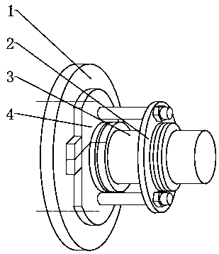
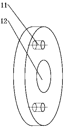
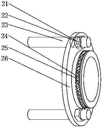
[0027] Specific embodiments: When the operator installs the limit block 4, first the upper half ring 43 and the lower half ring 46 of the limit block 4 rotate around the rotating shaft connecting the two, and the limit block 4 is installed on the concave hole on the shaft 3. In the groove, then rotate the limiting block 4 around the shaft 3 until the positioning block 42 is installed in the positioning hole 11, and realize the preliminary positioning of the limiting block 4 and the static ring end cover 1, and then screw the front of the upper half ring 43 The lower end of the bottom part is connected with the front upper end of the lower half ring, and finally the O-ring 2 44 is installed on the sealing ring groove 2 45. This design enables a better positioning between the limit block 4 and the static ring end cover 1 The connection solves the problem that the screw is broken due to 3 rotations of the shaft, which further affects the stability of the limit mechanism. In additi...


PUM


Abstract

The invention provides a mechanical seal limiting mechanism which comprises cylindrical holes, positioning blocks, an upper half ring, a second O-shaped ring, a second sealing ring groove, a lower half ring, nuts, through holes, locking cylinders and a fixing ring. The upper half ring is arranged at the upper end of the lower half ring, the two cylindrical holes are formed in the right end face of the upper half ring and the right end face of the lower half ring correspondingly, and the two positioning blocks are welded to the left end of the upper half ring and the left end of the lower half ring correspondingly. By means of the design, a limiting block and a static ring end cover can be better connected in a positioned mode, and the separable limiting block is more convenient to mount and dismount; the two through holes are symmetrically formed in the upper and lower ends of the interior of the fixing ring, and the locking cylinders penetrate through the through holes; and the nuts are mounted on the locking cylinders and fixed to the left end of the fixing ring. According to the design, when the limiting block loses efficacy, the limiting block can be prevented from moving, working stability is further guaranteed, and the mechanical seal limiting mechanism is good in stability, high in reliability, long in life and easy to mount and dismount.

Description

technical field [0001] The invention relates to a mechanical seal position limiting mechanism, which belongs to the field of position limiting mechanical equipment. Background technique [0002] In the prior art, a mechanical seal refers to a seal that is composed of at least one pair of end faces perpendicular to the axis of rotation, under the action of fluid pressure and the elastic force (or magnetic force) of the compensation mechanism, and the cooperation of the auxiliary seal to keep fit and slide relative to prevent fluid leakage. The mechanical seal limit mechanism is a mechanism that limits the movement of the mechanical seal. The traditional limit mechanism adopts a rectangular steel plate structure. The installation method is to drill a limit block hole on the rectangular limit block. Cover the machined threaded hole, then clamp one side of the limit block into the groove on the outer surface of the end of the mechanical seal sleeve, use a screw to pass through t...

Claims


Application Information

Patent Timeline
Patent Type & Authority Patents(China)
IPC IPC(8): F16J15/16
CPCF16J15/16
Inventor 赵声旺覃文覃水丽
Owner 中山市高泽模具有限公司
Why Eureka
Try Eureka