Blade non-contact local rapid heating constant speed breaking test technology for casing containment test
A non-contact, rapid heating technology, applied in the direction of engine testing, machine/structural component testing, measuring devices, etc., can solve the problems of easy interference between heating leads and thermocouple leads, long test process, long heating time, etc. Achieve the effects of shortening test preparation time and test implementation period, small heat-affected range, and simplified device structure
Inactive Publication Date: 2017-08-18
ZHEJIANG UNIV
View PDF7 Cites 11 Cited by
- Summary
- Abstract
- Description
- Claims
- Application Information
AI Technical Summary
Problems solved by technology
However, it is complicated to operate through the lead wire of the conductive slip ring. The lead wire of the thermocouple and the heater are easy to be disengaged or even broken during the high-speed rotation of the rotor. After the blades fly off, the unbalanced load of the rotor will damage the conducti
Method used
View moreImage
Smart ImageViewing Examples

Examples
 PUM
 Abstract
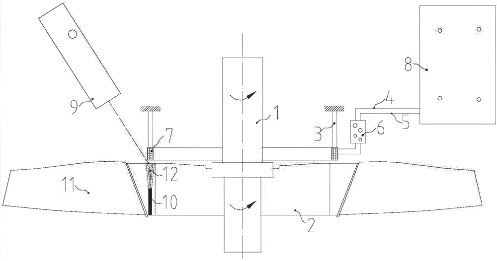
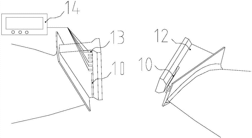
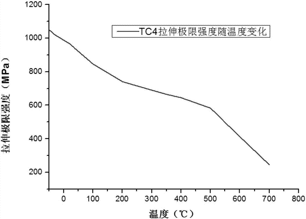
The invention discloses a blade non-contact local rapid heating constant speed fly-off test technology for casing containment test. A non-contact induction heating coil is installed on the end face of one side of the blade, and cracks are prefabricated on the other side of the blade. When the test rotor accelerates to the target speed and rotates stably, the control equipment is started, and the temperature in the local area of the weakened part of the blade rises rapidly. The ultimate tensile strength decreases, and the blade breaks and flies out under the action of centrifugal force. The method has high speed control accuracy, good reliability, short heating time, simple operation, high test precision, low test period and cost. The blade induction heating fly-off device includes induction heating control equipment, high-frequency induction coils, insulating fixing brackets, cooling water pipes, power lines, transfer ports, and infrared thermometers, etc., to monitor the surface temperature of the blade induction heating area under high-speed rotation Realized by infrared thermometer.
Description
technical field [0001] The invention relates to a blade non-contact local rapid heating constant-speed fly-off test technology for aero-engine fan and compressor casing containment tests, in particular to a blade fly-off speed accurate and predictable based on the principle of prefabricated cracks and induction heating Controlled vane break-off test technology at constant speed for casing containment test. Background technique [0002] For modern aviation aircraft, the flying off of fan blades is one of the most dangerous accidents. Flying off of the fan blades of an aeroengine can lead to engine damage, which may seriously endanger the integrity of the entire aircraft and the safety of passengers. The high-energy flying blade fragments may penetrate the casing, cut off the control cables, and penetrate the fuel tank and cabin. These may cause secondary damage such as aircraft control failure, fuel tank leakage and fire, and loss of pressure in the cabin, resulting in aircr...
Claims
Login to View More Application Information
Patent Timeline
 IPC IPC(8): G01M15/00
CPCG01M15/00
Inventor 宣海军罗灵范梦龙
Owner ZHEJIANG UNIV
Features
- R&D
- Intellectual Property
- Life Sciences
- Materials
- Tech Scout
- Unparalleled Data Quality
- Higher Quality Content
- 60% Fewer Hallucinations
Learn More Browse by: Latest US Patents, China's latest patents, Technical Efficacy Thesaurus, Application Domain, Technology Topic, Popular Technical Reports.
© 2025 PatSnap. All rights reserved.Legal|Privacy policy|Modern Slavery Act Transparency Statement|Sitemap|About US| Contact US: help@patsnap.com