Bladder tumor cutter

A technology of bladder tumor resection, which is applied in the field of bladder tumor cutter, can solve the problems of unresolved tumor tissue and floating tumor removal, and achieve the effects of reducing bleeding, compact device structure and convenient operation

Pending Publication Date: 2017-09-05
SECOND MILITARY MEDICAL UNIV OF THE PEOPLES LIBERATION ARMY
View PDF1 Cites 4 Cited by
  • Summary
  • Abstract
  • Description
  • Claims
  • Application Information

AI Technical Summary

Problems solved by technology

The invention has a simple structure and can remove larger tumors more completely, but

Method used


Image

  • Bladder tumor cutter
  • Bladder tumor cutter
  • Bladder tumor cutter

Examples


Example Embodiment

[0053] Example 1

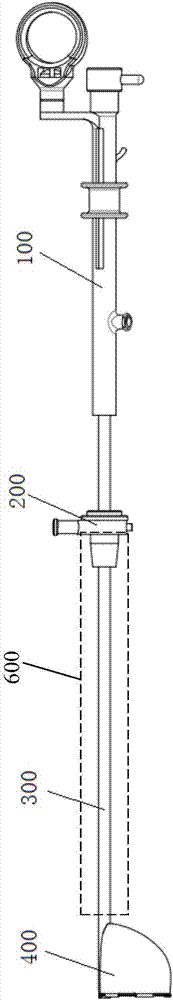
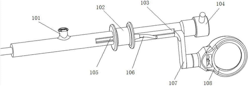
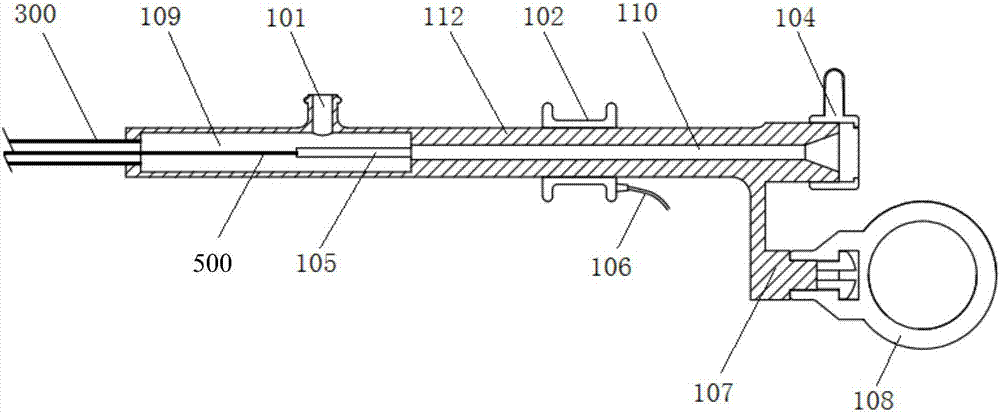
[0054] figure 1 Shown is a bladder tumor cutter in a preferred embodiment of the present invention, which includes a handle 100, a mirror sheath connector 200, a connecting tube 300, a storage bag 400 and a wire 500 (see image 3 ). Wherein, the handle 100 is connected to the rear end of the connecting tube 300 as a manipulation site for entraining and resecting the bladder tumor. The mirror sheath connector 200 is sleeved on the connecting tube 300. When in use, the connecting tube 300 extends into the mirror sheath 600. The mirror sheath connector 200 is used to connect with the mirror sheath 600. The mirror sheath 600 can be a conventional cystoscope sheath. It can be connected with the mirror sheath connecting head 200 in an existing common way. The storage bag 400 is connected to the front end of the connecting pipe 300 . The metal wire 500 is folded into double wires and threaded in the connecting pipe 300 along the axial direction.

[0055] like ...

Example Embodiment

[0067] Example 2

[0068] The difference between Embodiment 2 and Embodiment 1 lies in the setting of the storage bag 400, such as Image 6 As shown, the opening of the storage bag 400 and the connecting pipe 300 form an angle of 0° (that is, the opening of the bag is parallel to the connecting pipe. Of course, the metal wire can be bent to make the opening of the bag upward or downward according to actual needs), and the front end of the connecting pipe 300 Stretch in from the side wall of the storage bag 400 seamlessly, the front end of the wire 111 passes through the side wall above the front end of the connecting pipe 300, and the end of the connecting pipe 300 located in the storage bag 400 is provided with a drainage hole 302; tighten the wire 500 When the opening of the storage bag 400 is tightened, the front end of the connecting pipe 300 can be wrapped. In this embodiment, the water in the storage bag 400 can enter through the outlet 302 at the front end of the conne...

Example Embodiment

[0069] Example 3

[0070] The difference between Embodiment 3 and Embodiment 1 lies in the setting of the pulling member, including the setting of the slider 102 and the guide groove 103. The guide groove 103 is located on the side wall of the handle body 112 outside the first cavity 109, and the bottom of the guide groove 103 is located at the A protrusion is formed in a cavity 109 , and the through hole through which the connecting column 105 passes is located at the front end of the protrusion. The slider 102 is slidably fitted in the guide groove 103 by clipping.


PUM


Abstract

The invention discloses a bladder tumor cutter, which comprises a connecting tube, a metal wire and a handle, the metal wire is passed through the connecting tube, and the handle is connected to the rear end of the connecting tube; the connecting tube The front end is connected with a storage bag, and the front end of the metal wire is connected to the periphery of the pocket opening of the storage bag, and the part of the metal wire at the front edge of the pocket opening is exposed as an electric cutting wire; the handle includes a columnar handle body, the The main body of the handle is provided with a pulling piece, and the pulling piece is provided with a power cord; the two ends of the rear end of the metal wire pass through the side wall of the main body of the handle and are connected with the power cord. The bladder tumor harvester of the present invention can remove and collect tumors at different positions and volumes in the bladder as a whole through the wire and the storage bag, effectively reducing intraoperative bleeding, avoiding tumor floating, ensuring a clear and shortened surgical field of view The operation time can greatly reduce the difficulty of removing the tumor and the risk of tumor recurrence.

Description

technical field [0001] The invention belongs to the technical field of medical devices, and in particular relates to a bladder tumor cutter. Background technique [0002] Bladder tumor is a relatively common urological tumor at present. Its incidence and recurrence rate are increasing year by year, and the age of onset is also showing a younger trend, which obviously affects the quality of life and prognosis of patients. Treatment options for bladder tumors include TURBT, partial cystectomy, and total cystectomy. In most TURBT operations, the surgeon will face the situation of large tumor volume and wide base, etc., requiring the surgeon to resect the tumor multiple times and in pieces with a traditional resectoscope. However, during the resection process, the tumor is rich in Vascular tissue will cause a large area of ​​bleeding, which will obviously affect the operator's field of vision. In addition, the scattered tumor tissue floating in the bladder also aggravates the ...

Claims


Application Information

Patent Timeline
IPC IPC(8): A61B18/12A61B18/14A61B17/50
CPCA61B17/50A61B18/12A61B18/14A61B2018/00601A61B2018/00517A61B2018/144
Inventor 盛佳雁杨庆肖亮王珂男肖成武张超许传亮孙颖浩
Owner SECOND MILITARY MEDICAL UNIV OF THE PEOPLES LIBERATION ARMY
Why Eureka
Try Eureka