Automatic pin bending mechanism of electronic element

A technology of electronic components and bending mechanism, which is applied in the field of automatic pin bending mechanism, can solve the problems of insufficient automation, low efficiency, and high labor cost, and achieve the effects of improving production efficiency and quality, compact device mechanism, and saving installation space

Pending Publication Date: 2019-08-20
ZHUHAI ZHIXIN AUTOMATIC TECH CO LTD
View PDF0 Cites 4 Cited by
  • Summary
  • Abstract
  • Description
  • Claims
  • Application Information

AI Technical Summary

Problems solved by technology

[0002] Before the application of electronic components (such as radiators), the pins need to be bent. After the pins of the radiator are turned over, the bracket welds the pins of the radiator flatly on the circuit board during the

Method used


Image

  • Automatic pin bending mechanism of electronic element
  • Automatic pin bending mechanism of electronic element
  • Automatic pin bending mechanism of electronic element

Examples


Example Embodiment

[0023] This part will describe the specific embodiments of the present invention in detail, and the preferred embodiments of the present invention are shown in the accompanying drawings. Each technical feature and overall technical solution of the invention should not be construed as limiting the protection scope of the invention.

[0024] In the description of the present invention, it should be understood that the azimuth description, such as the azimuth or position relationship indicated by up, down, front, rear, left, right, etc., is based on the azimuth or position relationship shown in the drawings, only In order to facilitate the description of the present invention and simplify the description, it is not indicated or implied that the indicated device or element must have a particular orientation, be constructed and operated in a particular orientation, and therefore should not be construed as limiting the present invention.

[0025] In the description of the present in...


PUM


Abstract

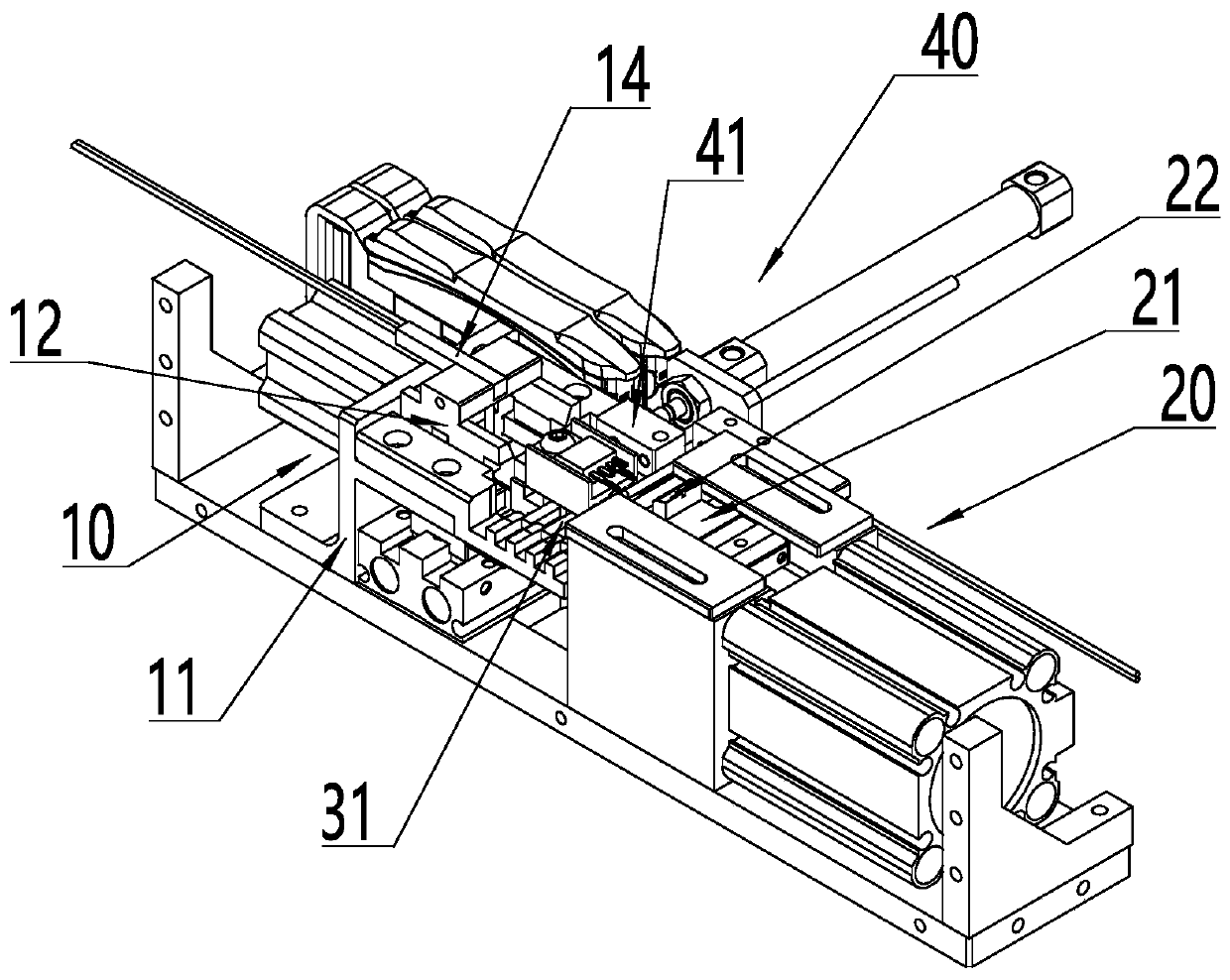
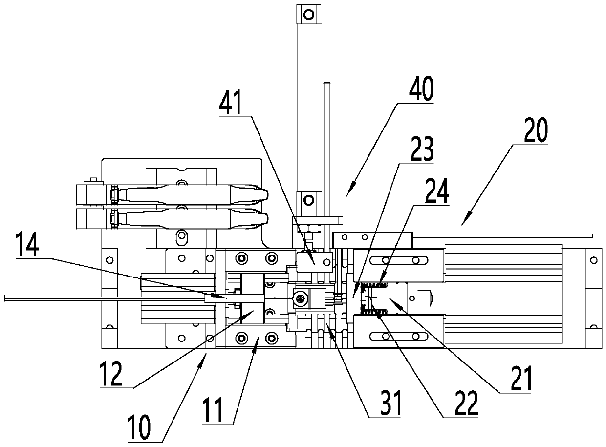
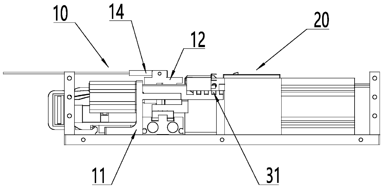
The invention discloses an automatic pin bending mechanism of an electronic element. The automatic pin bending mechanism comprises the following components of a holding device, a bending device, a discharging device, a pushing device, wherein the holding device comprises a fixing frame and a U-shaped retainer which is arranged on the fixing frame, and the retainer is arranged on the fixing frame through a first driving cylinder; the bending device comprises a pushing block, the pushing block is arranged on the side part of the fixing frame, and a bending head is arranged at one end, close to the holding frame, of the pushing block; the discharging device comprises an opening and closing block, and the movable opening and closing block is arranged below the fixing frame; the pushing devicecomprises a pushing block, and the pushing block is arranged at the side part of the fixing frame. Through the matching action of the retaining device, the bending device, the discharging device and the pushing device, the functions of workpiece positioning, pin bending, waste parts discharging and good parts blanking are realized, the device mechanism is compact, the installation space is saved,the pins can be quickly positioned and accurately bent, and the production efficiency and quality are improved.

Description

technical field [0001] The invention relates to the field of electronic component processing equipment, in particular to an automatic pin bending mechanism for electronic components. Background technique [0002] Before the application of electronic components (such as radiators), the pins need to be bent. After the pins of the radiator are turned over, the bracket welds the pins of the radiator flatly on the circuit board during the application process, which is convenient for fixing and suitable for automatic equipment production. Now Some radiator pin folding equipment has insufficient automation, low efficiency, and high labor costs in the production process. Contents of the invention [0003] The purpose of the present invention is to solve at least one of the technical problems existing in the prior art, and to provide an automatic pin bending mechanism for electronic components, which can make the device compact, save installation space, quickly locate and accuratel...

Claims


Application Information

Patent Timeline
IPC IPC(8): B21F1/00
CPCB21F1/00
Inventor 刘毓乾黄嘉良蒋兴峰张凡严炜冯艳生罗建明许广新李天玉
Owner ZHUHAI ZHIXIN AUTOMATIC TECH CO LTD
Why Eureka
Try Eureka