

Method for optimizing SAR antenna directional diagram test
An antenna pattern and pattern technology, applied in the field of optimization, can solve the problems of long test time, etc., and achieve the effect of speeding up the development progress and shortening the test time
- Summary
- Abstract
- Description
- Claims
- Application Information
AI Technical Summary
Problems solved by technology
Method used
Image


Examples
Embodiment Construction
[0017] The preferred embodiments of the present invention are given below in conjunction with the accompanying drawings to describe the technical solution of the present invention in detail.
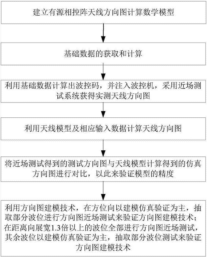
[0018] Such as figure 1 As shown, the method for optimizing the SAR antenna pattern test of the present invention comprises the following steps:
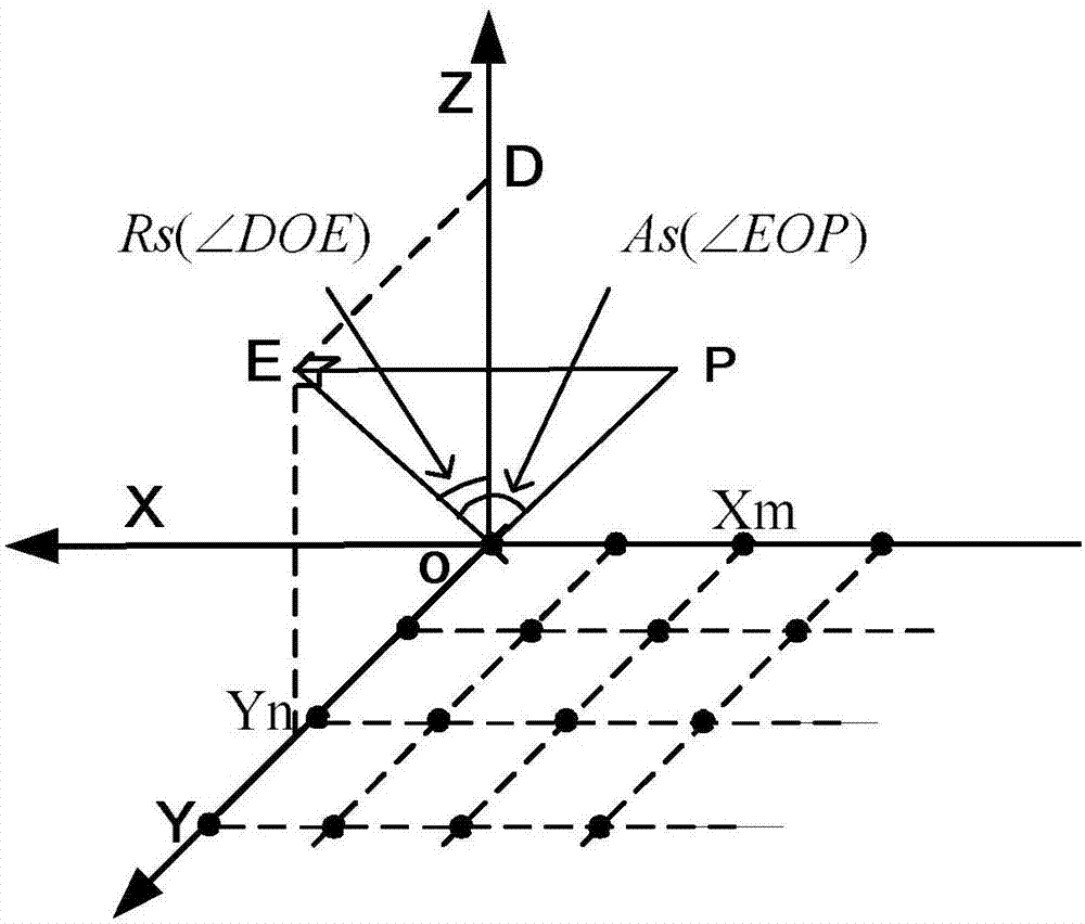
[0019] Step 1. First, establish the mathematical model for calculating the pattern of the active phased array antenna according to the electromagnetic field theory; the formula of the mathematical model for calculating the pattern of the active phased array antenna is shown in formula (1):
[0020]
[0021] in:
[0022] f mn is the electric field pattern of the antenna unit;
[0023] I mn is the amplitude excitation (amplitude distribution) of the antenna element;
[0024] A mn Amplitude errors due to feed network and components;
[0025] alpha mn is the failure factor of the antenna unit, and its value is only 0 or 1 (0 means failu...
PUM
 Abstract
Description
Claims
Application Information