Curved-rail-driven excavator bucket capable of adjusting earth excavating direction
A technology of arc-shaped rails and excavators, which is applied in the direction of mechanically driven excavators/dredgers, earth movers/shovels, construction, etc., which can solve the problem of dispersing the force of bucket digging and not being able to dig soil perpendicular to the ground And other issues
Active Publication Date: 2017-11-24
淄博北方压力容器制造有限公司
4 Cites 0 Cited by
AI-Extracted Technical Summary
Problems solved by technology
[0002] At present, in the field of excavator bucket technology, the use of excavators has brought a huge role to the development of human society, but it is also found that there are some problems in the excavator during use. When the traditional excavator bucket is digging, the bucket Sometimes the shovel teeth on the bucket body cannot excavat...
Abstract
The invention belongs to the technical field of excavator buckets and particularly relates to a curved-rail-driven excavator bucket capable of adjusting the earth excavating direction. The lower end of the bucket wall, where bucket teeth are mounted, of the bucket body is provided with a rotation hole. The plane formed by the axis of the rotation hole and the axis of a support lug connecting pin is perpendicular to the bevel of the inner wall, far from the support lug connecting pin, of the bucket body. The axis of the rotation hole and the intersecting line of the two planes coincide. By means of the design, the curved-rail-driven excavator bucket has the advantages that the radius of a curved rail rotating around a rotary pin is small, and the strength and stability of the bucket body are improved; the curved-rail-driven excavator bucket can effectively protect the bucket body and can enable the bucket body to bear larger force when excavating earth; a hydraulic motor drives the bucket body through the curved rail to rotate around the rotary pin, so that bucket teeth only bear force perpendicular to the bucket teeth from the ground; and the curved-rail-driven excavator bucket is simple in structure and good in practical effect.
Application Domain
Mechanical machines/dredgers
Technology Topic
EngineeringExcavator +1
Image
Examples
- Experimental program(1)
Example Embodiment
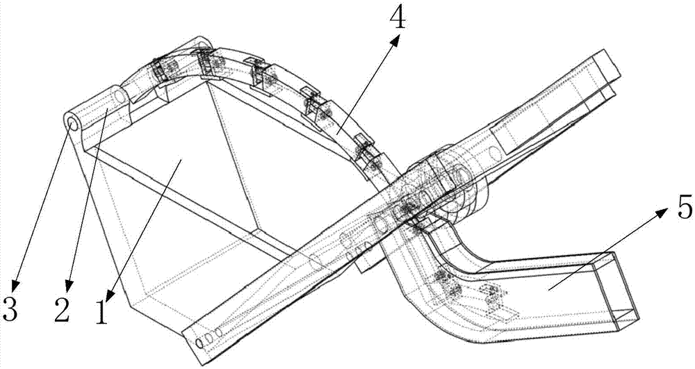
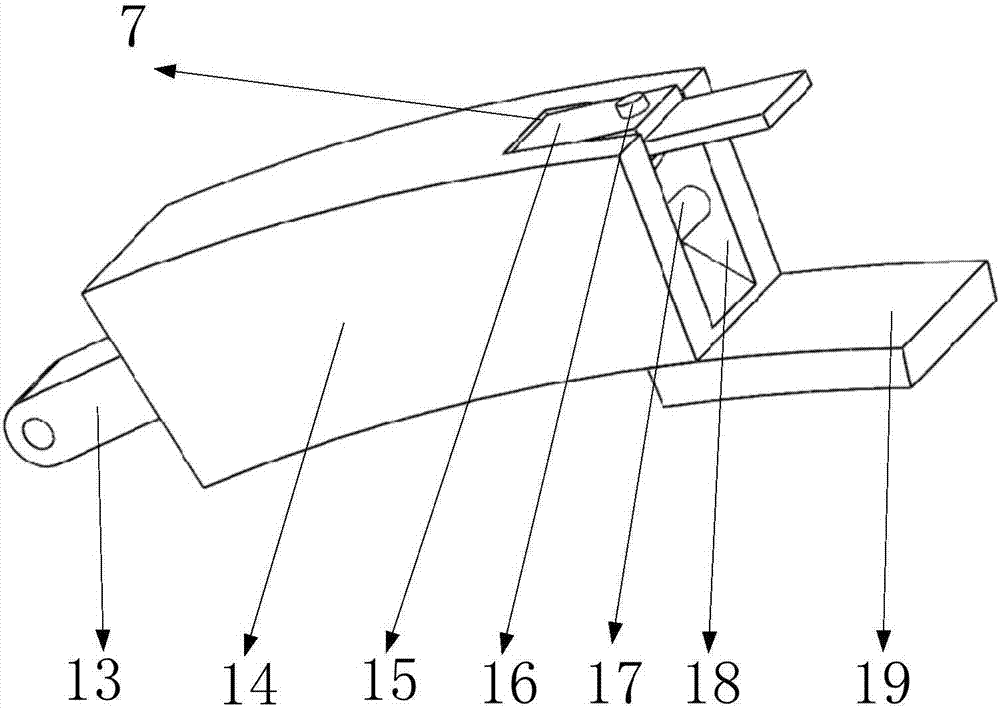
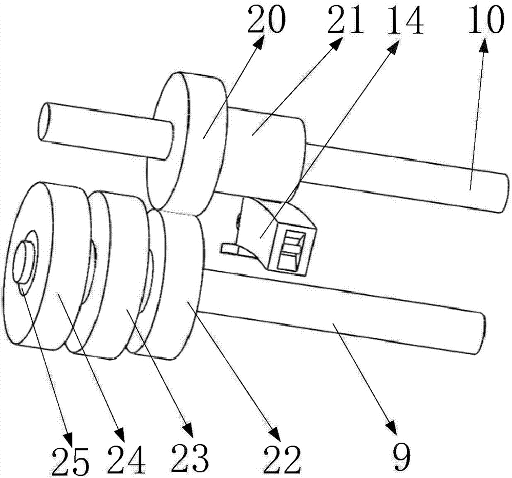
[0028] Such as Figure 5 , 6 As shown, it includes a bucket body 1, a bucket lug 2, a first one-way gear 62, a second one-way gear 63, a lug connecting pin 3, an arc rail 4, an arc rail bin 5, and a rotating hole 6. First bucket arm 8, first fixed post 9, second fixed post 10, bucket arm connecting plate 11, second bucket arm 12, first transmission gear 20, second transmission gear 21, third transmission Gear 22, hydraulic torque converter 23, hydraulic motor 24, transmission sleeve 25, rotating pin 26, shovel teeth 27, safety plate 28, bar groove 29, limit block 64, pressure plate 30, first gear 31, The first return spring 32, the second gear 33, the second telescopic rack 34, the fourth rack 35, the moving rod 36, the third gear 37, the fixed shaft 38, the third rack 39, the second return spring 40, the first A telescopic rack 41, mounting cavity 42, hydraulic oil storage cavity 43, connecting block 44, first hydraulic cylinder 45, trigger block 46, second hydraulic cylinder 47, first oil outlet 48, first oil outlet pipe 49, first Second oil outlet pipe 50, second oil outlet 51, third oil outlet 52, third oil outlet 53, fourth oil outlet 54, fourth oil outlet 55, oil inlet 56, oil outlet 57, T-shaped Slot 58, fixed plate 60, sliding block 61, such as Figure 5 As shown, two bucket lugs 2 are symmetrically installed on the upper end of the sloping wall on one side of the bucket body 1, and the two bucket lugs 2 are connected by lug connecting pins 3; Image 6 As shown, the lower end of the other side of the sloping wall of the bucket body 1 is provided with a rotating hole 6. The plane formed by the axis of the rotating hole 6 and the axis of the lug connecting pin 3 is perpendicular to the bucket body 1 away from the lug connecting pin 3 The inner wall is inclined, and the axis of the rotation hole 6 coincides with the intersection of the two planes; Figure 5 , 6 7. As shown in 7, the shovel tooth 27 is installed on the inclined wall of the bucket body 1; the shovel tooth 27 and the inside of the inclined wall have a mounting cavity 42; both sides of the shovel tooth 27 are opened with strip grooves 29; Image 6 , 14 As shown, the two safety plates 28 are each installed on the shovel teeth 27 through two connecting blocks 44, the connecting block 44 and the strip groove 29 are slidingly fitted, and the connecting block 44 is inserted and installed; Figure 14 As shown, two limiting blocks 64 are symmetrically installed on both sides of the connecting block 44, and the two limiting blocks 64 contact and cooperate with the inner wall of the mounting cavity 42; Picture 9 As shown, the first one-way gear 62 and the second one-way gear 63 are both mounted on the inner wall of the mounting cavity 42 through cylindrical pins; a fixing plate 60 is mounted on the side of the strip groove 29 on the inner wall of the mounting cavity 42; one end of the fixing plate 60 is mounted There are T-shaped blocks 65; Picture 12 As shown, both ends of the third rack 39 and the fourth rack 35 are provided with a T-shaped groove 58; the third rack 39 and the fourth tooth are both installed through the T-shaped groove 58 and the T-shaped block 65; Picture 12 As shown, a support spring 66 is installed in the T-shaped groove 58. One end of the support spring 66 is installed on the inner end surface of the T-shaped groove 58, and the other end is installed on the end surface of the T-shaped block 65; the first one-way gear 62 and the fourth rack 35 meshes, the second one-way gear 63 meshes with the third rack 39; Figure 5 , 6 As shown, the fixed shaft 38 is installed in the mounting cavity 42, the first gear 31, the second gear 33, and the third gear 37 are sequentially installed on the fixed shaft 38, and the first gear 31 meshes with the second one-way gear 63, The three gear 37 meshes with the first one-way gear 62; such as Figure 5 , 6 As shown, two pressure plates 30 are fixedly installed on two opposite inner walls of the mounting cavity 42 on the shovel teeth 27, and the two pressure plates 30 respectively cooperate with the corresponding safety plates 28; Figure 5 , 6 As shown, a first return spring 32 and a second return spring 40 are respectively installed on the end faces of the two pressure plates 30; Figure 5 , 6 As shown, a first telescopic rack 41 is installed on the first return spring 32, and the first telescopic rack 41 is meshed with the second gear 33; Picture 9 As shown, a second telescopic rack 34 is installed on the second return spring 40, and the second telescopic rack 34 meshes with the second gear 33; Picture 9 As shown, the end of the first telescopic rack 41 away from the first return spring 32 is fixedly installed on the compressed plate; Image 6 As shown, one end of the second telescopic rack 34 away from the second return spring 40 is fixedly installed on the pressure plate 30; the lower sides of the first telescopic rack 41 and the second telescopic rack 34 are installed with a moving rod 36; the trigger block 46 is installed On the lower end surface of the mounting cavity 42, a first hydraulic cylinder 45 is installed on the upper end surface of the trigger block 46; Image 6 As shown, the lower end of the moving rod 36 is in contact with the upper end surface of the trigger block 46; Picture 8 As shown, the trigger block 46 has a cavity inside, such as Picture 8 As shown, the sliding block 61 is installed in the cavity; Picture 8 As shown, a second hydraulic cylinder 47 is installed between the inner end surface of the trigger block 46 and the sliding block 61; Picture 8 As shown, the upper end surface of the trigger block 46 is successively installed with a first oil outlet pipe 49, a second oil outlet pipe 50, a third oil outlet pipe 53, and a fourth oil outlet pipe 54. The lower end surface has two oil inlet ports 56 and oil outlet ports 57. ;Such as Picture 8 As shown, the first oil outlet pipe 49, the second oil outlet pipe 50, the third oil outlet pipe 53, and the fourth oil outlet pipe 54 are all connected to the hydraulic motor 24 through pipes; Picture 8 As shown, the upper end surface of the sliding block 61 is sequentially opened with a first oil outlet 48, a second oil outlet 51, a third oil outlet 52, and a fourth oil outlet 55. Two hydraulic oil storages are symmetrically opened on the lower side. Cavity 43; such as Picture 8 As shown, the oil inlet 56 and the oil outlet 57 respectively communicate with a hydraulic oil storage cavity 43; the first oil outlet 48 and the third oil outlet 52 are connected to the hydraulic oil storage cavity with the oil inlet 56 through a hose 43 connection, the second oil outlet 51 and the fourth oil outlet 55 are connected to the hydraulic oil storage chamber 43 communicating with the oil outlet 57 through a hose; both the oil outlet 57 and the oil inlet 56 are connected to the hydraulic system of the excavator ;Such as Figure 5 As shown, the rotating pin 26 passes through the rotating hole 6, and both ends of the rotating pin 26 are equipped with a first bucket arm 8, such as figure 1 , 5 As shown, the two first bucket arms 8 are both located outside the bucket body 1; Figure 5 As shown, a first fixed column 9, a second fixed column 10, and a bucket arm connecting plate 11 are installed between the two bucket arms, and the first fixed column 9, the second fixed column 10, and the bucket arm connecting plate 11 are respectively installed. Distributed in sequence relative to the rotating pin 26; image 3 As shown, the second bucket arm 12 is installed on the bucket arm connecting plate 13; the first transmission gear 20 and the second transmission gear 21 are both installed on the second fixed post 10; image 3 As shown, the fixed outer ring of the hydraulic motor 24 is installed on the first fixed column 9, the transmission sleeve 25 is nested on the first fixed column 9, and the transmission sleeve 25 is installed on the rotating inner ring of the hydraulic motor 24, the hydraulic torque converter 23 and the third transmission gear 22 are sequentially installed on the transmission sleeve 25, the first transmission gear 20 and the third transmission gear 22 are meshed; the hydraulic motor 24 is connected to the hydraulic system of the excavator through a hose; Figure 4 As shown, the arc-shaped rail bin 5 is installed on the first fixed column 9; Figure 5 As shown, one end of the arc-shaped rail 4 is installed on the lug connecting pin 3, and the other end is located in the arc-shaped rail compartment 5, and the arc-shaped rail 4 is matched with the second transmission gear 21; Figure 13 As shown, the second hydraulic cylinder 47 and the first hydraulic cylinder 45 are connected via a hose.
[0029] Such as Figure 5 As shown, the arc-shaped rail 4 includes a telescopic plate slot 7, a connecting plate 13, an arc-shaped shell 14, a trigger telescopic plate 15, a trigger switch 16, a cylindrical bar 17, a rotating cavity 18, and a stop 19, such as Figure 5 As shown, the arc-shaped rail 4 is formed by connecting arc-shaped shells 14, and the arc-shaped shells 14 are connected by connecting plates 13; figure 2 , 11 As shown, the upper end of the arc-shaped shell 14 is provided with teeth, both ends of the arc-shaped shell 14 are provided with a rotating cavity 18, and the teeth opened on the arc-shaped shell 14 mesh with the second transmission gear 21; figure 2 , 11 As shown, a cylindrical strip 17 is installed in the rotating cavity 18, and the cylindrical strip 17 and the connecting plate 13 rotate and cooperate; figure 2 , 11 As shown, a telescopic plate slot 7 is opened at the upper end of one side of the arc-shaped shell 14, the trigger-type telescopic plate 15 is installed in the telescopic plate slot 7, and the trigger-type telescopic plate 15 is in contact with the adjacent arc-shaped shell 14; figure 2 , 11 As shown, a trigger switch 16 is installed on the upper end of the trigger telescopic board 15; figure 2 , 11 As shown, one end of the stopper 19 is installed at one end of the lower side of the arc-shaped shell 14, and the other end is in contact with the arc surface of the lower side of the adjacent arc-shaped shell 14.
[0030] The above-mentioned first transmission gear 20 and second transmission gear 21 are mounted on the second fixed column 10 using bearings.
[0031] The above-mentioned third transmission gear 22 is installed on the transmission sleeve 25 through a key.
[0032] The aforementioned first return spring 32 and second return spring 40 are compression springs.
[0033] Such as Picture 10 As shown in a, 11, when the bucket body 1 is not working, the trigger type telescopic plate 15 is in the extended state, so the arc-shaped rail 4 presents a circular arc shape.
[0034] In summary:
[0035] In the present invention, the plane formed by the axis of the rotating hole 6 and the axis of the lug connecting pin 3 is perpendicular to the inner wall slope of the bucket body 1 away from the lug connecting pin 3, and the axis of the rotating hole 6 coincides with the intersection of the two planes; this design The main function is to make the radius of the arc-shaped rail 4 rotate around the rotating pin 26 small, and increase the strength and stability of the bucket body 1 wall; the rotating pin 26 is opened on the bucket body 1 wall where the shovel teeth 27 are installed, so that When the bucket body 1 is digging the soil, it rotates relative to the rotation pin 26 so that the shovel teeth 27 can be perpendicular to the ground. The wall of the bucket body 1 with the shovel teeth 27 installed on the bucket body 1 will not be affected by the soil layer. Under pressure, the shovel teeth 27 will only receive the force perpendicular to the ground, which can effectively protect the bucket and enable the bucket to withstand greater force when digging; the role of the hydraulic torque converter 23 is to reduce the torque. When the bucket body 1 digs harder things, reduce the speed and increase the torque, so that the bucket body 1 can dig the soil with greater force; the function of the trigger type telescopic plate 15 is to During the movement of the arc-shaped shell 14 in the rail compartment 5 under the drive of the second transmission gear 21, when the second transmission gear 21 rotates to contact the trigger switch 16, the trigger telescopic plate 15 will Extend, to withstand the next arc-shaped shell 14, so that the next arc-shaped shell 14 cannot swing, and enables the second transmission gear 21 to pass through the gap between the two arc-shaped shells 14; the function of the stopper 19 is to block Adjacent to the arc-shaped shell 14, the arc-shaped shell 14 cannot swing, so that the arc-shaped shell 14 can form the arc-shaped rail 4. The function of the arc-shaped rail warehouse 5 is to store the arc-shaped shell 14 that is not driven by the second transmission gear 21 to prevent When the bucket body 1 is digging, the arc shell 14 affects the digging of the bucket body 1; the transmission sleeve 25 is installed on the rotating inner ring of the hydraulic motor 24, and the third transmission gear 22 is installed on the transmission sleeve 25. The transmission gear 22 meshes with the first transmission gear 20, the second transmission gear 21 meshes with the arc rail 4, and the hydraulic motor 24 provides power to move the arc rail 4, driving the bucket body 1 to rotate relative to the rotating pin 26, and the bucket The bucket body 1 excavates soil; the function of the curved rail 4 is to transmit the power of the hydraulic motor 24, so that the bucket body 1 rotates relative to the rotating pin 26 for excavation; the function of the pressure plate 30 and the trigger block 46 is, So that when the bucket teeth 27 are not perpendicular to the ground, the trigger block 46 affects the rotation of the hydraulic motor 24, so that the bucket teeth 27 can be perpendicular to the ground for shoveling operations; the first return spring 32 and the second The function of the second return spring 40 is that when the pressure receiving plate 30 is moved under pressure, the first telescopic rack 41 and the second telescopic rack 34 will not interfere with each other; the function of the safety plate 28 is to identify whether the tooth 27 is perpendicular to Digging the ground; the function of the pressure plate 30 is that when the bucket body is not perpendicular to the ground, the safety plate 28 installed on the shovel teeth 27 will be under pressure, so that the safety plate 28 will be on the shovel The teeth 27 slide on the outer wall. At this time, the movement of the safety plate 28 will be transmitted to the pressure plate 30, so that the first telescopic rack 41 and the second telescopic rack 34 move, the first extension of the movement The retractable rack 41 and the second retractable rack 34 will exert pressure on the force plate. Since the tooth 27 is not perpendicular to the ground at this time, the outer wall of the tooth 27 on one side will contact the ground. The pressure plate 30 will exert a force on the wall of the shovel tooth 27, thereby achieving the effect of strengthening the strength of the shovel tooth 27; the function of the oil circuit cooperation between the first hydraulic cylinder 45 and the second hydraulic cylinder 47 is to move the moving rod 36 It is transmitted to the sliding block 61, and the corresponding oil outlet 57 and the oil outlet pipe are matched by the sliding of the sliding block 61 to control the forward and reverse rotation of the hydraulic motor 24.
[0036] The specific implementation is that when the equipment of the present invention is used for shoveling operations, such as Picture 10 As shown in b, the shovel teeth 27 are perpendicular to the soil surface and enter the soil. The hydraulic system of the excavator drives the hydraulic motor 24 to work, the hydraulic motor 24 drives the transmission sleeve 25 to rotate, and the transmission sleeve 25 drives the third transmission gear 22 to rotate, and the third transmission gear 22 Drive the first transmission gear 20 to rotate, the first transmission gear 20 drives the second transmission gear 21 to rotate, and the second transmission gear 21 drives the arc rail 4 to move, so that the arc rail 4 drives the bucket body 1 through the lug connecting pin 3 Rotate relative to the rotating pin 26, such as Picture 10 As shown in c, the bucket body 1 at this time begins to excavate soil, until the bucket body 1 turns parallel to the ground, the hydraulic motor 24 stops rotating, and the bucket body 1 ends when the second transmission gear 21 When driving the arc-shaped rail 4 to move, the second transmission gear 21 first drives the arc-shaped housing 14 to move. As the second transmission gear 21 rotates, the second transmission gear contacts the trigger switch 16 on the arc-shaped housing 14, so that the trigger type The telescopic plate 15 extends and bears the next arc-shaped shell 14; the second transmission gear 21 enters the next arc-shaped shell 14 through the trigger-type telescopic plate 15; the second gear 33 continues to rotate so that the arc-shaped shell 14 moves from the arc-shaped rail The arcuate rail 4 is formed out of the bin 5, so that the second transmission gear 21 meshes with the arcuate rail 4 to drive the arcuate rail 4 to move; when the shovel teeth 27 are not vertical to the ground to shovel soil, and the bucket body 1 is away from the excavator When the operator is tilted; the safety plate 28 will move along the strip groove 29 under the force of the soil, the moving safety plate 28 will drive the connecting block 44 mounted on it to move, and the connecting block 44 will push the third rack 39 movement; the third rack 39 will drive the second one-way gear 63 to move, the second one-way gear 63 will drive the first gear 31 to move, the first gear 31 will drive the fixed shaft 38 to move, and the fixed shaft 38 will move Will drive the second gear 33 and the third gear 37 to move, and the second gear 33 will drive the second telescopic rack 34 to move. The moving second telescopic rack 34 will exert a pressure on the pressure plate 30, thereby making the The pressure plate 30 will reinforce the shovel teeth 27 so that the shovel teeth 27 can withstand greater force from the soil; the moving second telescopic rack 34 will drive the moving rod 36 to move; compress the first return spring 32 to drive the moving rod 36 moves laterally to compress the first hydraulic cylinder 45. The first hydraulic cylinder 45 drives the second hydraulic cylinder 47 to expand and contract through a hose, pushing the sliding block 61 to move, so that the first oil outlet 48 and the first oil outlet pipe 49 are connected. The third oil outlet 52 and the third oil outlet pipe 53 are connected. The hydraulic oil in the hydraulic oil storage chamber 43 enters the hydraulic motor 24 through the first oil outlet pipe 49 through the hose, and drives the hydraulic motor 24 to rotate, making the bucket body 1 Rotate so that the shovel teeth 27 can shovel the soil perpendicular to the ground; when the shovel teeth 27 are not perpendicular to the ground and the bucket body 1 is tilted toward the operator of the excavator; the safety plate 28 will move along with the force of the soil. When the strip groove 29 moves, the moving safety plate 28 will drive the connecting block 44 mounted on it to move, so that the connecting block 44 will in turn drive the fourth rack 35, the first one-way gear 62, and the third Gear 37, second gear 33, first gear 31, first telescopic rack 41, second telescopic rack 34; the moving first telescopic rack 41 and second telescopic rack 34 will drive the moving rod 36 to move; The moving rod 36 will stretch the first hydraulic cylinder 45. The first hydraulic cylinder 45 drives the second hydraulic cylinder 47 to expand and contract through a hose, pushing the sliding block 61 to move, so that the second oil outlet 51 and the second outlet The oil pipe 50 is connected, the fourth oil outlet 55 and the fourth oil pipe 54 are connected, the hydraulic oil storage cavity The hydraulic oil in 43 passes through the hose and enters the hydraulic motor 24 through the second oil outlet pipe 50, and drives the hydraulic motor 24 to reverse, so that the bucket body 1 rotates, so that the shovel teeth 27 can shovel the soil perpendicular to the ground; When it is perpendicular to the ground, the safety plate 28 will not move, and the bucket will continue to shovel; when the bucket body 1 is filled with soil and starts to pour the soil, the hydraulic motor 24 reverses so that the curved rail 4 follows the shovel When the soil moves in the opposite direction, the bucket body 1 rotates relative to the rotating pin 26 so that the soil is poured out of the bucket body 1.
PUM


Description & Claims & Application Information
We can also present the details of the Description, Claims and Application information to help users get a comprehensive understanding of the technical details of the patent, such as background art, summary of invention, brief description of drawings, description of embodiments, and other original content. On the other hand, users can also determine the specific scope of protection of the technology through the list of claims; as well as understand the changes in the life cycle of the technology with the presentation of the patent timeline. Login to view more.