
Constructional engineering horizontal calibrator

A level calibrator, construction engineering technology, applied in the direction of height/level measurement, instruments, surveying instruments, etc., can solve the problems of time-consuming and laborious, unable to reach the calibrator, increased difficulty of construction work, etc.

Inactive Publication Date: 2017-12-01
衢州万鹏环境建设有限公司
View PDF12 Cites 0 Cited by
  • Summary
  • Abstract
  • Description
  • Claims
  • Application Information

AI Technical Summary

Problems solved by technology

[0002] At present, most of the leveling measurements in construction projects use a transparent tube, fill the transparent tube with water, and estimate the height difference after visually measuring the distance between the horizontal planes. This operation is very imprecise, and the operation is very troublesome and time-consuming. , which increases the difficulty of construction work. For example, the patent application No. 201220350600.7 includes a transparent tube, which is characterized in that a telescopic rod is provided on the outside of both ends of the transparent tube, and a vertical measuring ruler is provided at the front end of the telescopic rod. Although it can accurately judge the height The difference distance reduces the difficulty of construction work, but it cannot meet the effect that the calibrator can be placed on any object, cannot avoid the problem that the calibrator can only be placed horizontally, and cannot achieve the effect that the calibrator can perform horizontal calibration from multiple angles

Method used


Image

  • Constructional engineering horizontal calibrator
  • Constructional engineering horizontal calibrator
  • Constructional engineering horizontal calibrator

Examples


Embodiment Construction

[0014] The following will clearly and completely describe the technical solutions in the embodiments of the present invention with reference to the accompanying drawings in the embodiments of the present invention. Obviously, the described embodiments are only some, not all, embodiments of the present invention. Based on the embodiments of the present invention, all other embodiments obtained by persons of ordinary skill in the art without making creative efforts belong to the protection scope of the present invention.

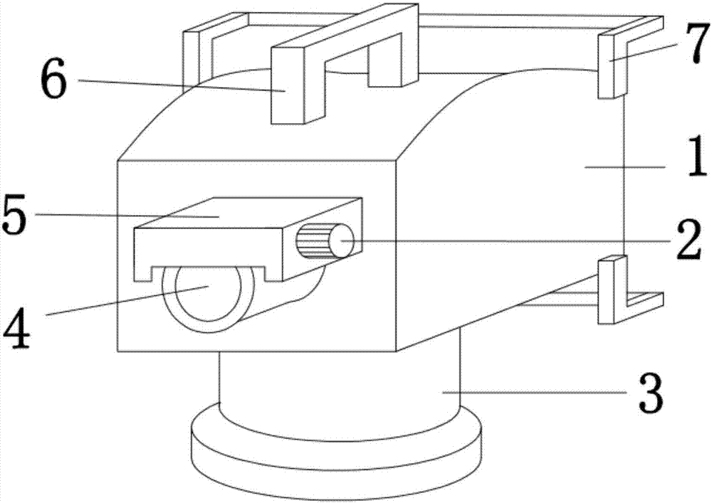
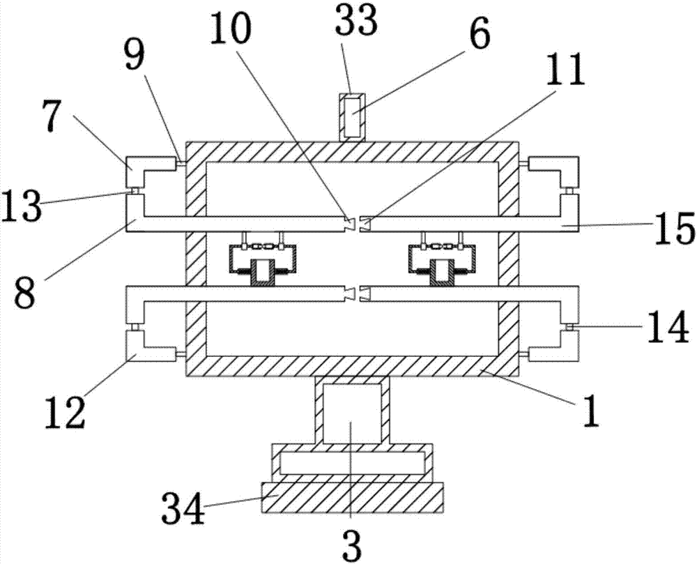
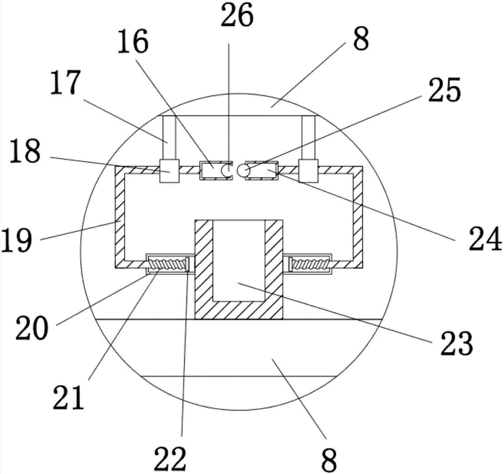
[0015] see Figure 1-4 , the present invention provides a technical solution: a leveling device for construction engineering, including an instrument body 1, a handle 6 is provided on the top of the instrument body 1, and the handle 6 is lifted so that the instrument body 1 can move, and the front of the instrument body 1 An observation mirror 4 is installed at the center, and the observation mirror 4 can observe the horizontal situation. The top of the observ...


PUM


Abstract

The invention discloses a constructional engineering horizontal calibrator which comprises an instrument body, wherein a handle is arranged at the top end of the instrument body; an observation mirror is mounted in the center of the front surface of the instrument body; a protection cover is arranged at the top end of the observation mirror; first L-shaped rods are arranged on the left side and the right side of the top end of the rear surface of the instrument body; a first L-shaped plate is connected with the instrument body through a first rotating shaft; second L-shaped rods and fourth L-shaped rods are arranged at the left ends and the right ends of the lower parts of the first L-shaped rods; the second L-shaped rods and the fourth L-shaped rods are both connected with the first L-shaped rods through second rotating shafts; clamping blocks are arranged on the right sides of the second L-shaped rods; clamping grooves are formed in the left sides of the fourth L-shaped rods; and third L-shaped rods are formed in the left side and the right side of the bottom end of the rear surface of the instrument body. The constructional engineering horizontal calibrator has the effect that the calibrator can be arranged on any article in a sleeve manner, the problem that the calibrator can be only placed horizontally is avoided, and the effect that horizontal calibration in multiple angles is achieved by using the calibrator is achieved.

Description

technical field [0001] The invention relates to the technical field of construction engineering level calibrator, in particular to a construction engineering level calibrator. Background technique [0002] At present, most of the leveling measurements in construction projects use a transparent tube, fill the transparent tube with water, and estimate the height difference after visually measuring the distance between the horizontal planes. This operation is very imprecise, and the operation is very troublesome and time-consuming. , which increases the difficulty of construction work. For example, the patent application No. 201220350600.7 includes a transparent tube, which is characterized in that a telescopic rod is provided on the outside of both ends of the transparent tube, and a vertical measuring ruler is provided at the front end of the telescopic rod. Although it can accurately judge the height The difference in distance reduces the difficulty of construction work, but...

Claims


Application Information

Patent Timeline
Patent Type & Authority Applications(China)
IPC IPC(8): G01C5/00G01C15/00
CPCG01C5/00G01C15/00
Inventor 章小春
Owner 衢州万鹏环境建设有限公司
Learn More