Eureka AIR delivers breakthrough ideas for toughest innovation challenges, trusted by R&D personnel around the world.

Radome test device

A test device and radome technology, which is applied to the measurement device, the casing of the measurement device, the measurement power and other directions, can solve the problems of distortion of test results, unreasonable structural design of the radome test device, etc., and achieves the effect of solving the unreasonable structural design.

Pending Publication Date: 2017-12-19
KUANG CHI INST OF ADVANCED TECH
View PDF0 Cites 10 Cited by
  • Summary
  • Abstract
  • Description
  • Claims
  • Application Information

AI Technical Summary

Problems solved by technology

[0004] The main purpose of the present invention is to provide a radome testing device to solve the problem that the structure design of the radome testing device in the prior art is unreasonable, and then the test result is distorted when the radome testing device performs a test with an aiming error

Method used


Image

  • Radome test device
  • Radome test device
  • Radome test device

Examples


Embodiment Construction

[0031] It should be noted that, in the case of no conflict, the embodiments in the present application and the features in the embodiments can be combined with each other. The present invention will be described in detail below with reference to the accompanying drawings and examples.

[0032] The following will clearly and completely describe the technical solutions in the embodiments of the application with reference to the drawings in the embodiments of the application. Apparently, the described embodiments are only some of the embodiments of the application, not all of them. The following description of at least one exemplary embodiment is merely illustrative in nature and in no way serves as any limitation of the application, its application or uses. Based on the embodiments in this application, all other embodiments obtained by persons of ordinary skill in the art without creative efforts fall within the protection scope of this application.

[0033] It should be noted ...


PUM


Abstract

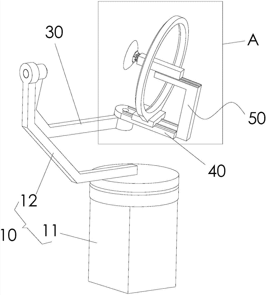
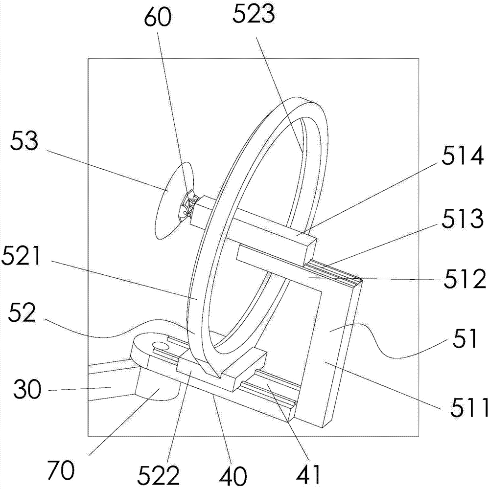
The invention provides a radome test device. The device comprises a rotation support, a first rotation arm, a second rotation arm and a test connection portion, wherein the rotation support is rotatably arranged about a first axis; the first rotation arm is pivotally arranged on the rotation support, and the first rotation arm can rotate about a second axis; the second rotation arm is pivotally arranged on the first rotation arm, and the second rotation arm can rotate about a third axis; and the test connection portion is arranged on the second rotation arm. In the prior art, the structure of the radome test device is designed unreasonably so that a test result has a distortion problem when the radome test device carries out testing with a pointing error. In the technical scheme of the invention, the above problem is solved.

Description

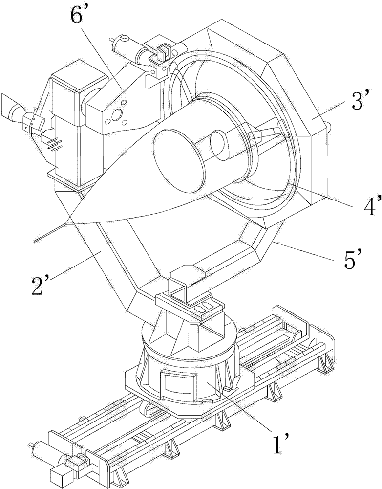
technical field [0001] The invention relates to the technical field of communication testing, in particular to a radome testing device. Background technique [0002] The radome test turntable in the prior art is generally provided with an azimuth turntable 1', a pitch support frame 2', a pitch axis, a radome support 3', a radome polarization swivel 4', an antenna support 5', an antenna azimuth axis, Antenna pitch axis and other mechanisms. Among them, such as figure 1 As shown, the azimuth turntable 1' is placed at the bottom end, which can drive the turntable to rotate around the azimuth axis as a whole, and is used for adjusting the azimuth angle of the radome and scanning the azimuth. The pitch support frame 2' is installed on the turntable and is the main load-bearing component of the radome. The pitch axis is installed on the pitch bracket, the pitch arm 6' is installed on the pitch axis, the radome bracket 3' is fastened to the pitch arm 6', and the pitch axis can d...

Claims


Application Information

Patent Timeline
IPC IPC(8): G01R31/00G01R1/02G01R1/04
CPCG01R1/02G01R1/04G01R31/00
Inventor 不公告发明人
Owner KUANG CHI INST OF ADVANCED TECH
Why Eureka
Eureka Blog
Learn More