Supercharge Your Innovation With Domain-Expert AI Agents!

Braking modified structure

A technology of improved structure and brake block, which is applied to bicycle accessories, bicycle brakes, etc., can solve the problems of increasing the braking force, changing the braking effect, and not being able to automatically increase the brake clamping force, so as to increase the brake clamping force and lift the brake. effect of motion

Active Publication Date: 2018-02-02
曾东荣
View PDF5 Cites 0 Cited by
  • Summary
  • Abstract
  • Description
  • Claims
  • Application Information

AI Technical Summary

Problems solved by technology

[0004] However, the above-mentioned brake structure used in bicycles can only drive the braking arm to generate the clamping force required for braking. On the whole, there is no design to further increase the braking force, so the overall braking effect It changes with the operator's hand or wrist grasping and grasping force, and cannot automatically increase the brake clamping force

Method used


Image

  • Braking modified structure
  • Braking modified structure
  • Braking modified structure

Examples


Embodiment Construction

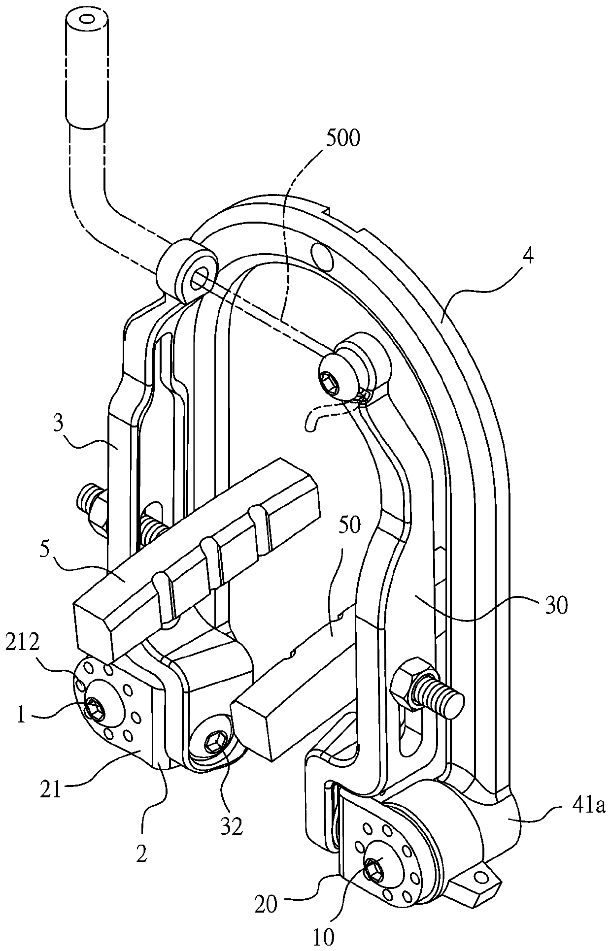
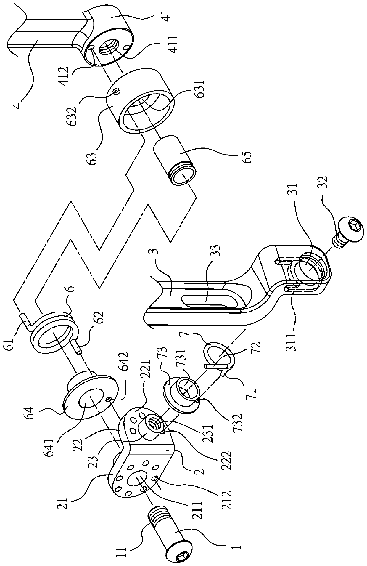
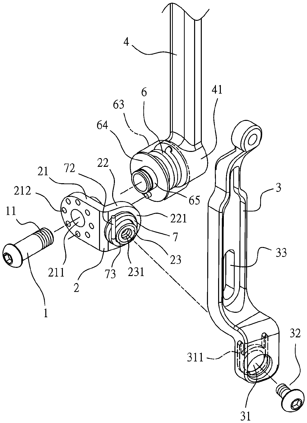
[0083] See Figure 1 to Figure 5 As shown, it can be seen that the first embodiment of the present invention takes the form of a bicycle as an example. The main structure includes two main shaft bolts 1, 10, two receiving parts 2, 20, and two clamp arms 3, 30, etc.; wherein the main shaft bolt 1 One end is provided with an external thread 11; in this embodiment, there is another U-shaped bracket 4 fixed on the bicycle frame. The two ends of the bracket 4 extend on both sides of the wheel and are respectively provided with the same seat 41, 41a, a threaded hole 411 perpendicular to the wheel axis is provided on the seat 41, and at least one recessed hole 412 is provided beside the threaded hole 411, and the outer thread 11 of each spindle bolt 1 is screwed into each threaded hole 411, The spindle bolt 1 can be coupled to the seat 41 in a direction perpendicular to the wheel axis.

[0084] The spindle bolt 10 has the same structure as the spindle bolt 1 and can be combined on the s...


PUM


Abstract

Disclosed is a braking modified structure. The braking modified structure is used for clamping and braking a wheel and at least comprises two symmetrical connecting parts and two clamping arms. Each connecting part is provided with a first side part and a second side part which are bent and extend. The first side parts are pivoted on main shaft bolts located on the two sides of the wheel and perpendicular to a wheel shaft. Each second side part is provided with a guide bevel which gradually approaches the wheel in the radial direction of the wheel. Each guide bevel is provided with a verticalconvex extending auxiliary shaft part. The two clamping arms are pivoted on the two auxiliary shaft parts correspondingly. The middle section of each clamping arm is combined with a braking block. When the ends, away from the auxiliary shaft parts, of the two clamping arms are close to each other, the other ends of the two clamping arms are linked up with the two connecting parts to rotate on themain shaft bolts in a pivoted mode, so that the two braking blocks are in contact friction with a wheel ring, and by using the braking blocks to be linked up with the two clamping arms to rotate alongall the guide bevels in the pivoted mode, the braking blocks are further forced to tighten the wheel ring.

Description

Technical field [0001] The present invention relates to a brake structure for a vehicle, in particular to an improved brake structure that can automatically increase the clamping force and improve the overall braking effect. Background technique [0002] Known brake structures for bicycles, such as the two types of C brakes (C clamps) and V brakes (V clamps) that are common on the market. In the case of V brakes, it is used at the double fulcrums on both sides of the wheel rim Axle-actuated brakes are provided with a pair of detent arms. The two detent arms are respectively pivotally connected to the frame pins located on both sides of the bicycle wheel by a coupling assembly, and are arranged in groups on the inner sides of the lower ends of the two detent arms. There is a brake block, and a suspension wire frame is arranged above the two lever arms. The suspension wire frame is connected with the brake suspension wire to control the two lever arms; during operation, the brake w...

Claims


Application Information

Patent Timeline
Patent Type & Authority Applications(China)
IPC IPC(8): B62L1/14
CPCB62L1/14
Inventor 曾东荣
Owner 曾东荣
Features
  • R&D
  • Intellectual Property
  • Life Sciences
  • Materials
  • Tech Scout
  • Unparalleled Data Quality
  • Higher Quality Content
  • 60% Fewer Hallucinations
Learn More